Stop guessing why your CNC machining costs are exploding. This in-depth DFM (Design for Manufacturability) guide gives you the exact data to prove why the internal sharp corners vs. radius debate is the #1 driver of your part cost.
We’ll show you precisely how to optimize your design before you ever get a quote.
The real impact of internal sharp corners vs. radius is that true sharp corners (R0) are physically impossible for standard CNC milling and require a separate, high-cost EDM process. Even reducing a radius (e.g., from R3mm to R0.5mm) causes an exponential, not linear, increase in CNC machining cost, time, and creates critical stress concentration points that lead to part failure.
In this guide, I’ll share the hidden “L/D ratio” trap most engineers fall into and give you 3 simple design solutions (like the “dog-bone” fillet) you can use today to eliminate these costs.
The “Exponential” Penalty: Quantifying the Cost from R3mm to R0

You need hard data to justify your design decisions to project managers and clients. So, let’s stop speaking in generalities and look at the real numbers.
The real impact of your radius choice isn’t a simple linear increase. As you shrink that radius, the CNC machining cost and time don’t just go up—they escalate exponentially.
Why? Because you’re forcing the machinist to use progressively smaller, slower, and more fragile tools.
Let’s use a common example: a 6061 aluminum pocket with a depth of 20mm. Look at how the cost and risk profile changes dramatically with each small design change.
Manufacturing Cost & Risk Analysis: Internal Radius (20mm Pocket Depth)
| Your Design Radius | Required Tool (Example) | L/D Ratio (Risk) | Estimated Cost/Time Impact | Our Manufacturing Notes (The “Why”) |
|---|---|---|---|---|
| R3mm (Safe Zone) | D6mm (Standard Tool) | 3.3:1 (Low Risk) | 1x (Baseline Cost) | Efficient, stable, great surface finish. This is the goal. |
| R1mm (Warning Zone) | D2mm (Long-Neck Tool) | 10:1 (High Risk) | 3x – 5x Cost | Tool will chatter. Feed rate must be slow. High risk of tool breakage. |
| R0.5mm (Danger Zone) | D1mm (Specialty Tool) | 20:1 (Extreme Risk) | 8x – 15x Cost | This isn’t manufacturing; it’s a gamble. Tool cost is high, and part failure rate is significant. |
| R0 (Sharp Corner) | CNC + EDM | N/A | 10x – 20x+ Cost | This is a punitive quote. Requires a second, costly, and slow Electrical Discharge Machining (EDM) process. |
As you can see, the jump from R1mm to R0.5mm is far more severe than the jump from R3mm to R1mm.
That tiny R0.5mm radius requires a tool with a 20:1 length-to-diameter (L/D) ratio. This tool is long, thin, and will vibrate (or “chatter”) significantly, resulting in poor surface finish and dimensional inaccuracy—all while running painfully slow to avoid snapping.
And what about the internal sharp corner ($R0$)? You’ve just forced the part into an entirely different, multi-step manufacturing process. It must be milled and then taken to a completely different machine (an EDM) for a slow, electrical erosion process. The cost explodes.
The 3 “Hidden Costs” That Won’t Appear on Your Quote
That exponential cost table is just the beginning. The real impact of small-radius corners is hidden in three cost centers that won’t ever be a line item on your quote. But you are absolutely paying for them.
1. The Depth Trap (The L/D Ratio)
Here’s a critical mistake we see engineers make all the time: they only look at the radius, not the depth of the pocket.
The truth is, a shallow R1mm pocket (say, 3mm deep) is cheap. But an R1mm pocket that is 30mm deep? That’s a different beast entirely.
The real manufacturing driver isn’t the radius alone; it’s the L/D ratio—the tool’s cutting length (L) divided by its diameter (D). To cut your R1mm corner (requiring a D2mm tool) inside a 30mm deep pocket, you need a tool with an L/D ratio of 15:1.
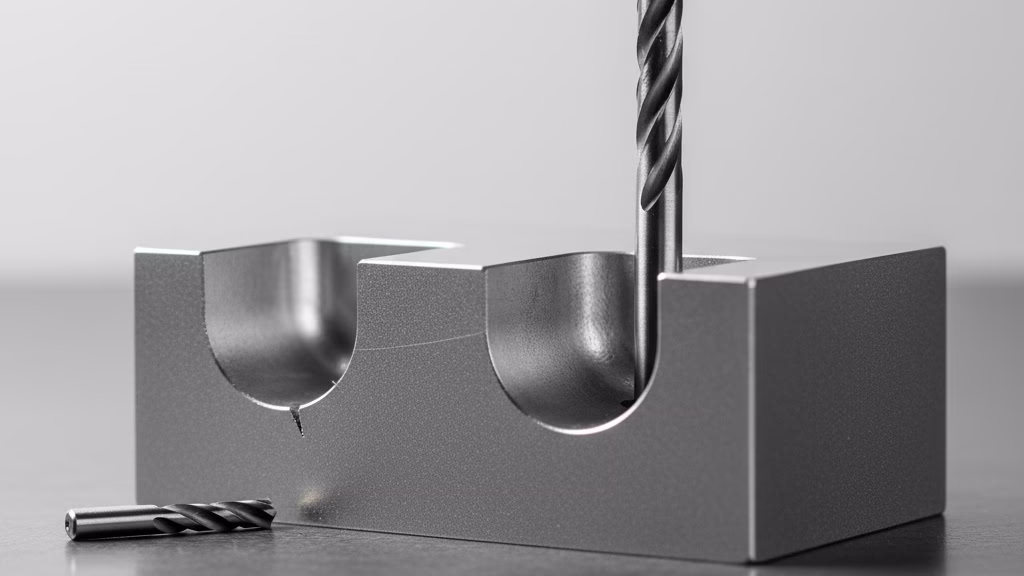
This is what that looks like. It’s a long, fragile, $85 specialty tool that’s built to vibrate.
As Peter Zelinski, Editor-in-Chief of Modern Machine Shop, puts it, “Every shop lives by the L:D ratio… When a designer specs a very small radius… at the bottom of a deep pocket, they are creating a nightmare scenario. This requires a long, skinny tool. The tool will deflect, it will chatter, and you have to slow the feed rate to almost zero… It’s not just slower; it’s a high-risk operation.”
That “chatter” (vibration) will destroy your surface finish and make it impossible to hold tight tolerances.
2. The “Invisible” Cost: CAM Programming Time
You might assume your part’s cost is just materials + machine time. That’s incorrect.
A huge part of the cost is CAM programming time—the high-skilled labor of a manufacturing engineer telling the machine what to do.
- Your R3mm Pocket: A programmer imports your file, clicks a standard “pocket” operation, and the software automatically generates a safe, efficient toolpath in 5 minutes.
- Your R0.8mm Deep Pocket: This is a manual, 1-hour job for a senior programmer. They must create multiple toolpaths: first, a large “roughing” tool to clear material, then a “semi-finishing” tool, and finally, that fragile D1.6mm “finishing” tool. They must manually tweak speeds, feeds, and entry points for this final tool to prevent it from snapping.
You are paying for that programmer’s hour, and it’s just as expensive as the machine’s time.
3. The “EDM Penalty”: It’s Not a Surcharge, It’s a Stop-Work Cost
Finally, what if you do specify that R0 internal sharp corner? You might assume the cost is just (CNC Milling Cost) + (EDM Cost).
This is a critical misunderstanding.
In a professional machine shop, the expensive, high-precision EDM machines are not sitting idle. They are high-value assets, running 24/7 on complex, high-profit jobs like injection mold cavities.
When your simple aluminum part with one sharp corner arrives, it has to interrupt that high-value work.
Your quote doesn’t just reflect the cost of the EDM process. It includes a “punitive” or “opportunity” cost—the price the shop charges to stop their most profitable work to handle your “line-cutting” part. You’re not paying for an “add-on”; you’re paying to compensate the shop for the money they aren’t making on a mold while they’re running your part instead.
The Fatal Risk: Why Sharp Corners Are “Functional Suicide”
The real impact of your corner choice goes far beyond CNC machining cost and time. We’re now entering the domain of your core responsibility as an engineer: part reliability.
Choosing a sharp or near-sharp corner isn’t just expensive; it’s often a functional failure waiting to happen.
A Physics Warning: The Peril of Stress Concentration
Let’s pull out our engineering textbooks. An internal sharp corner ($R \to 0$) is a theoretical “infinite stress concentration point.”
In the real world, any load, vibration, or impact your part experiences will focus all its force directly onto that single, sharp point.
Imagine a stress map: a proper radius (like R3mm) diffuses the load beautifully, showing a calm, distributed green. A sharp corner lights up bright red, indicating a critical point of failure.
For any part under cyclic load (like a bracket or support) or subject to impact, this is a fatal flaw. It is not a question of if it will fail, but when. The fatigue crack will always begin at that sharp corner.
A Real-Life Lesson: Our Client’s $R0.25mm Failure
We learned this lesson firsthand with a client, a fitness equipment company.
- The Pitfall: They designed a key load-bearing bracket that had to mate with an off-the-shelf sensor. This required an $R0.25mm$ internal corner. We strongly advised against it, explaining the L/D ratio risk and the stress concentration problem.
- The Insistence: The client, under pressure to hit their launch date, couldn’t change the sensor. They rejected our DFM advice and asked us to proceed, accepting the risk.
- The Result: We manufactured the parts. They passed dimensional inspection perfectly. Three months later, we received a call from their VP of Engineering. During high-cycle fatigue testing, 100% of the brackets had failed, with the crack originating exactly at that $R0.25mm$ radius.
This taught us a crucial lesson: our job isn’t just to “make parts to print.” Our true value is to use our manufacturing experience to prevent our clients from making critical, costly failures.
The Takeaway: Adding a generous radius isn’t “caving” to your supplier to save them money. It’s you, the engineer, buying reliability insurance for your own design. The cost of a small design change pales in comparison to the cost of a product recall.
Master Your Design Before Manufacturing
These design traps can derail your project. Before you finalize your CAD, let our engineers provide a free DFM analysis to identify costly mistakes (like deep pockets or risky L/D ratios) and ensure your design is optimized for cost and reliability.
The Ultimate Solution: 3 Decisions When You Must Use a Sharp Corner
This is the question we get every week: “I understand all this. But my design must interface with a square-mating component. What do I actually do?”
When a sharp corner is a true functional requirement, you have a clear, three-path decision tree. Here are your solutions, from best to worst.
Solution 1 (The Optimal Choice): Design a “Dog-Bone” Fillet
This is the most efficient and clever solution. A dog-bone fillet is a design “cheat” where you intentionally add a circular toolpath beyond the corner. This creates a small, recessed area that allows your square component to slide in and make full contact with the flat walls, while the internal corner of your part remains rounded.
- How it works: You’re simply adding a few seconds of machine time for the end mill to cut a circle.
- The Value: It is 100% completed on the CNC mill in the same setup. The added cost is negligible (often less than 5%). It perfectly solves the functional problem.
- Best for: Any internal, non-cosmetic feature. This is the preferred engineering solution 90% of the time.
Solution 2 (The Smart Redesign): Use a Two-Part Assembly
This solution requires you to step back and rethink the design itself. Can that one complex part be redesigned as two simpler parts that are assembled with bolts or screws?
- How it works: Instead of one component with a complex internal pocket (requiring a tiny, deep tool), you now have two simpler parts. One part might be a flat plate, and the other a U-shaped block. Both can be machined quickly with large, standard tools.
- The Value: You completely eliminate the problematic internal corner. While you’ve added an assembly step, the total manufacturing cost for the two simple parts can be 40% (or more) lower than the one complex part.
- Best for: Housings, enclosures, or complex assemblies where this design change is feasible.
Solution 3 (The Last Resort): Specify EDM
This is your final option. If the sharp internal corner is on a critical, customer-facing “A-Surface” where neither a dog-bone nor a two-part assembly is acceptable, then you must specify Electrical Discharge Machining (EDM).
- How it works: You are now committing to the multi-step, high-cost process we discussed earlier.
- The Value: It will give you a true, sharp corner.
- The Cost: You must be prepared to absorb the 10x to 20x cost increase and the 2-3 day lead time extension. This decision should only be made when the aesthetic or functional requirement is absolute and the budget allows for it.
Conclusion: Become a Partner, Not Just a “Quoter”
As an engineer, one of your biggest frustrations is the “technical chasm”—that feeling of helplessness when you receive a high quote with no explanation, or a simple “cannot be made.” You’re left guessing why it’s so expensive and what to do about it.
This is the critical difference between a simple supplier and a true manufacturing partner.
- A supplier sees your internal sharp corner, prices in the high-cost EDM process, and sends you the “punitive” quote.
- A partner sees the same sharp corner and calls you. They’ll ask, “Is this corner a functional necessity? If so, have you considered a dog-bone fillet? It could save you 40%.”
As the engineering team at Protolabs, a global leader in digital manufacturing, states, “Attempting to machine a sharp internal corner with a round tool is physically impossible. The alternative is Electrical Discharge Machining (EDM), a secondary process that introduces significant time and cost.”
A partner’s job is to use their experience to help you avoid that secondary process at all costs.
Our value isn’t just in the machines we own. Our true value is our decades of manufacturing experience that we use to optimize your design before the first chip is cut. We’d rather spend 15 minutes on a call with you discussing a radius change than waste 5 hours of machine time (and your budget) on a high-risk, low-efficiency toolpath.
Don’t Bear the DFM Burden Alone
Stop guessing at the real impact of your design choices. Before you finalize your next part, let us help you bridge that gap between design and manufacturability.
Send us your CAD file. We’ll provide a free, actionable DFM review focused specifically on your internal sharp corners vs. radius choices. We will show you exactly where you can optimize your design to dramatically reduce your CNC machining cost and time—giving you the data and confidence you need to make the right call.
References & Notes
[1] L/D Ratio (Length-to-Diameter): This critical machining metric defines the ratio of the tool’s cutting length (L) to its diameter (D). A high L/D ratio (e.g., 10:1) results in significantly reduced tool rigidity, leading to chatter, poor surface finish, and a high risk of tool breakage, thus exponentially increasing machining time and cost.
[2] Stress Concentration: A well-established principle in mechanical engineering where stress in an object is significantly higher around discontinuities such as corners, holes, or notches. A sharp internal corner (R→0) acts as a stress raiser, theoretically approaching an infinite concentration of stress, making it the primary point of failure for parts under cyclic load or impact.
[3] Electrical Discharge Machining (EDM): A non-traditional manufacturing process that uses electrical discharges (sparks) to obtain a desired shape. It is used to machine hard metals or shapes that are impossible to achieve with standard milling, such as true internal sharp corners. It is highly accurate but significantly slower and more costly than CNC milling.