Frustrated by project costs spiraling out of control due to a single tolerance callout? This guide moves beyond simple data charts to introduce a proven DfM framework. It’s designed to transform your decision-making process, empowering you to make confident design choices that lead to predictable costs and profitable projects.
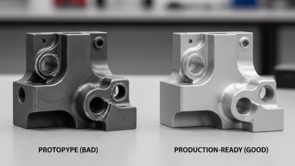
Costly tolerance drawing mistakes include applying unnecessary tight tolerances that can double manufacturing costs, overlooking material hardness post-heat-treatment which forces expensive secondary grinding operations, and specifying a blanket surface finish instead of targeting only critical functional areas, leading to avoidable process time.
Spotting these common errors is only half the battle. The real key to consistent, cost-effective design lies in a simple decision-making matrix that top project leads use to balance performance and budget. What follows isn’t just a list of tips; it’s the system that will fundamentally change how you approach the relationship between cost, surface finish, and function.
Stop Choosing Processes. Start Defining Thresholds.

For decades, the central question for designers facing a high-precision surface has been, “Should I use milling or grinding?”
This is the wrong question.
The most significant leap you can make in your design philosophy is to stop prioritizing the process and start defining the purpose. The truly transformative question isn’t about how a part is made, but why a specific tolerance is needed in the first place.
This brings us to the core of our DFM masterclass: The “Functional Threshold First” Framework.
The core idea is this: Your primary job as a designer is not to pursue theoretical perfection, but to determine the absolute minimum requirement—the functional threshold—that a surface must meet to perform its job reliably over its intended lifespan.
Instead of asking, “What process should I choose?” you should be asking, “What is the worst acceptable state this surface can be in and still function flawlessly?” This simple reframing shifts your role from a passive process selector to an active cost-benefit analyst. It forces a deeper level of engineering inquiry that moves beyond the numbers on a drawing and into the real-world physics of your assembly.
The Cost of Crossing the Threshold
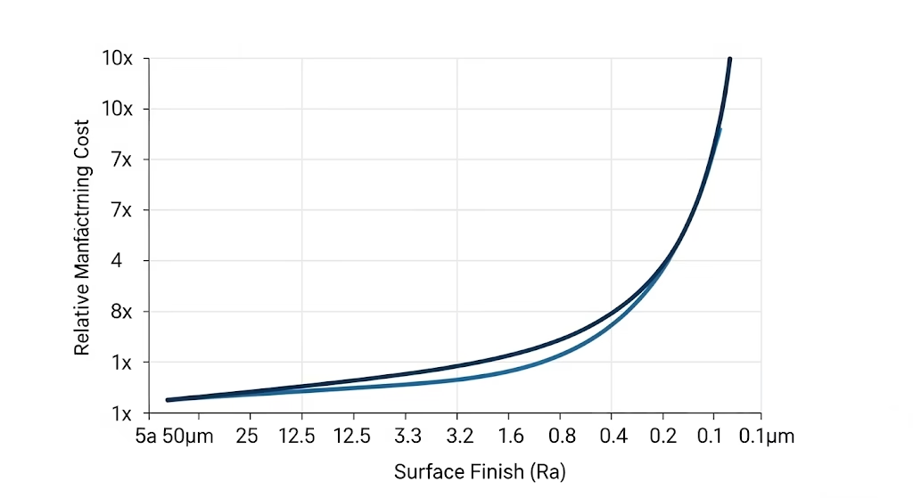
So, what is a “threshold”? It’s the critical tipping point where the manufacturing cost curve goes from a gentle slope to a vertical climb. For many milling processes, that threshold is a surface finish of Ra 0.8µm (or ~32 µin). This is a crucial distinction compared to our CNC milling tolerances.
Surfaces rougher than this can often be achieved with standard, cost-effective CNC milling. But the moment your design requires a finish smoother than this, you cross a threshold and enter a new cost paradigm.
The relationship isn’t linear; it’s exponential, a concept we explore in our deep dive into the costs of Ra 0.8µm vs. Ra 0.4μm finishes.
To illustrate this, we use a simplified “Surface Finish Cost Index” to explain the dramatic, non-linear price increase:
CostFinish = CostBase × 2.1( (0.8 / RaTarget) – 1 )
- CostBase is the baseline cost to achieve a standard milled finish of Ra 0.8µm.
- RaTarget is your desired, smoother surface finish.
- The exponent 2.1 is the crucial factor. It reveals the brutal reality of chasing perfection.
Let’s see it in action:
- Improving the finish from Ra 0.8µm to Ra 0.4µm (a 2x improvement) more than doubles the cost.
- Improving it further from Ra 0.4µm to Ra 0.2µm (another 2x improvement) will double the cost again.
The designer often seeks a linear improvement in performance but is met with an exponential penalty in cost. Your goal is to stay on the flat part of that cost curve for as many features as possible, only crossing the threshold when the functional demands are absolute and undeniable.
From Fear-Based Design to Simulation-Backed Confidence
Why has “tighter is better” been the default for so long? Historically, tight tolerances acted as a physical safety factor—a way to compensate for the fear of unknown variables like stress, vibration, and thermal expansion.
However, a hidden connection is changing this equation: the rise of accessible, high-fidelity simulation tools like Finite Element Analysis (FEA) directly within your CAD platform.
The confidence you gain in the digital world directly translates to the tolerance you can afford to relax in the physical world.
A well-executed simulation provides a “digital twin” of your part, predicting its real-world performance with incredible accuracy. When your FEA results show that stress levels are well within the safe zone, you gain the data-backed confidence to step back from unnecessarily tight tolerances.
The simulation becomes your new safety factor, replacing the outdated and expensive crutch of over-tolerancing. This allows you to design based on evidence, not on fear.
The 3-Step DFM Blueprint for Tolerances
| Key DFM Question | Milling Approach (Cost-Effective) | Grinding Approach (High-Precision) |
|---|---|---|
| Primary Goal | Shape generation, material removal | Ultimate precision, superior finish |
| When to Use It? | Ra > 0.8µm, Tolerances > ±0.015mm | Ra < 0.8µm, Tolerances < ±0.015mm |
| Core Problem Solved | Cost-effective part creation | Overcoming heat-treat distortion |
Theory is powerful, but action is what drives results. Now that you’ve embraced the “Functional Threshold First” framework, it’s time to apply it. This three-step blueprint will transform that “Aha!” moment into a repeatable, systematic process you can use on every design.
Step 1: How to Isolate Your “Money Surfaces”
Not all surfaces on a part are created equal. Some are simple clearance faces, while others are mission-critical bearing surfaces. The first step is to differentiate between them and focus your “tolerance budget” only where it creates value. We call the critical surfaces the “Money Surfaces”—the ones where precision directly impacts function.
Use this checklist to identify them:
- Is it a Mating Surface? Does this surface contact another part in the assembly?
- Is it a Dynamic Surface? Does this surface move against another part (e.g., a piston in a bore, a shaft in a bearing)? Understanding how to achieve a precision bore is critical for the reliability of these dynamic systems.
- Is it a Sealing Surface? Does this surface form a seal with a gasket, O-ring, or another component?
- Is it a Locating Surface? Is this surface a primary datum used to locate other features or components?
If you answer “yes” to any of these, you’ve found a Money Surface. Every other surface is likely a “non-functional surface,” where tolerances can and should be relaxed to the standard shop floor level (e.g., ISO 2768-m).
Step 2: The Tolerance Triage: A Quick Decision Chart for Milling vs. Grinding
Once you’ve identified your Money Surfaces, use this triage chart to quickly categorize the manufacturing process required. This chart helps you visualize the thresholds we discussed earlier and make a data-driven decision.
| Requirement Category | Standard Milling | Precision Milling / Hard Milling | Grinding Required |
|---|---|---|---|
| Surface Finish (Ra) | > 1.6µm (63 µin) | 0.8µm – 1.6µm (32 – 63 µin) | < 0.8µm (32 µin) |
| Typical Tolerance | ±0.05mm (±0.002″) | ±0.015mm – ±0.05mm (±0.0006″ – ±0.002″) | < ±0.015mm (±0.0006″) |
| Material Hardness | < 45 HRC | 45 – 60 HRC (Specialized) | > 55 HRC (Post Heat-Treat) |
| Typical Application | Clearance holes, non-critical faces, structural components. | Mating faces, tight-fit pockets, some bearing fits. | High-speed bearing surfaces, hydraulic piston rods, precision dowel fits, sealing surfaces. |
| Relative Cost | 1x (Baseline) | 1.5x – 3x | 3x – 10x+ |
Step 3: Case Study: How to Communicate Intent on Your Drawing
Your drawing is not just a set of instructions; it’s a conversation with your manufacturer. Ambiguity is the enemy of efficiency. After using the first two steps to make your decisions, the final step is to communicate them with absolute clarity. This is where you combine precise GD&T with clear, human-readable notes.
This is a point Greg Paulsen, Director of Application Engineering at the manufacturing platform Xometry, emphasizes constantly:
We often see features that are over-toleranced not for function, but because it’s a ‘copy-paste’ from a previous design or a default CAD setting. This is a classic DFM (Design for Manufacturability) disconnect. The designer’s intent is risk-aversion, but the unintended consequence is a massive cost increase. The key is to ask ‘why’ for every tight tolerance. Is it for fit, function, or fear? If it’s the latter, there’s almost always a more cost-effective way to achieve the same result.
Let’s look at how this all comes together in the “scanning arm” case study we mentioned at the beginning.
- The Initial Request: A client developing a high-end automated inspection device sent us a drawing for a critical “scanning arm.” The design called for the entire component to be heat-treated to 60 HRC and then the entire main face ground to a smooth Ra 0.4µm finish. This was a classic “insurance policy” design—safe, but extremely expensive.
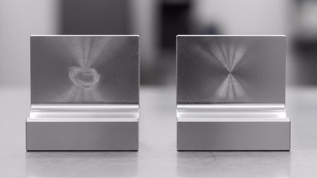
- Our Value-Added Insight: Applying the DFM blueprint, our engineers immediately isolated the “Money Surfaces”—two narrow 5mm-wide tracks on the main face that made contact with the guide rails. The other 80% of the surface was non-functional. We proposed a counter-intuitive but far more efficient plan:
- Machine the entire face using high-speed CNC milling to a perfectly acceptable Ra 0.8µm.
- Use induction hardening to locally harden only the two 5mm tracks to the required 60 HRC.
- Precisely grind only those two hardened tracks to the required Ra 0.4µm.
- The Superior Outcome: The client trusted our DFM expertise and approved the change. The results were dramatic and went far beyond what they expected:
- 35% Cost Reduction: By eliminating hours of grinding on non-functional surfaces, we drastically cut the cost of the most expensive manufacturing step.
- 40% Faster Delivery: The total cycle time dropped from 15 days to just 9, allowing the client to accelerate their prototype testing.
- Unexpected Performance Boost: Because the main body of the arm wasn’t subjected to the high stress of a full-body heat treatment, it had significantly better dimensional stability. This happy accident resulted in a more reliable assembly that required less frequent calibration.
Need to Hold the Tightest Tolerances?
Our Precision Grinding Services are engineered for applications where absolute accuracy is non-negotiable. We help you correct heat-treat distortions and achieve superior surface finishes.
Are Your Tools Creating a Hidden Risk?
You now have the framework and the blueprint to master the technical decisions around tolerances. You know how to isolate your Money Surfaces, use the triage chart, and clearly communicate your intent. This knowledge alone puts you in the top tier of design engineers.
But after you optimize the part, a new, more strategic question emerges: How do you optimize your manufacturing partnerships?
In the age of instant uploads and automated online quoting platforms, we’ve gained incredible speed. But this convenience has created a subtle, second-order risk that most engineers don’t see. While these platforms are brilliant at calculating the cost of geometry, they are completely blind to design intent.
An algorithm can tell you that loosening a tolerance will save you $10. It cannot, however, warn you that loosening that specific tolerance might cause harmonic vibrations that lead to premature bearing failure. A human expert can. This leads to a dangerous trap: “algorithmic cost optimization.” Engineers can find themselves tweaking designs to please a quoting algorithm, shaving a few dollars here and there, without a deeper, consultative DFMs conversation about the consequences of those changes.
The true path to manufacturing excellence isn’t just optimizing your design; it’s building a relationship with a partner who understands your goals. Use instant quoting platforms as a directional compass for cost, but not as a replacement for expert navigation on your most critical components.
Your Partner in Precision
Ultimately, the complex relationship between tolerances for grinding vs. milling isn’t just a technical challenge—it’s a conversation about value, risk, and intent. By moving beyond a fear-based “tighter is better” mindset and adopting a “Functional Threshold First” approach, you can save money, reduce lead times, and build better, more reliable products.
The next step is to find a manufacturing partner who thinks the same way.
Stop looking for a simple order-taker and start looking for a strategic advisor. Look for a team that doesn’t just read your drawing, but understands your vision, challenges your assumptions, and helps you navigate the complex trade-offs between cost and performance. Because in the world of high-precision manufacturing, the right conversation is always more valuable than the lowest quote.
Frequently Asked Questions (FAQ)
What Ra value absolutely requires grinding?
As a general rule, any surface finish requirement smoother than Ra 0.8µm (32 µin) will almost certainly require a grinding operation, especially on hardened materials. While some advanced milling techniques can approach this number in softer materials, grinding is the only reliable and consistent method for achieving finer finishes.
How much more expensive is grinding than milling?
The cost can vary dramatically, but it’s not uncommon for grinding to be 3 to 10 times more expensive than standard milling for the same feature. The cost increases due to slower material removal rates, higher setup complexity, more expensive machinery, and the need for highly skilled operators.
Can CNC milling achieve a mirror finish?
No. A true mirror finish (typically Ra 0.025-0.05µm) cannot be achieved by milling. Milling is a cutting process that will always leave microscopic tool marks. To achieve a mirror finish, secondary processes like lapping and polishing are required after the initial milling or grinding operations.
What are the typical tolerances for grinding?
Precision grinding can consistently hold extremely tight dimensional and geometric tolerances, with achieving tight tolerances with CNC grinding being a key benefit.
It’s common to see tolerances in the range of ±0.002mm to ±0.005mm (±0.0001″ to ±0.0002″). For some specialized applications like gage making, even tighter tolerances are possible.