Spécifiez en toute confiance l'état de surface le plus rentable pour vos pièces usinées par CNC. Ce guide fournit les données, les aperçus DFM et les conseils d'experts dont vous avez besoin pour choisir entre une finition Ra 0,8μm et Ra 0,4μm sans sacrifier les performances ou le budget.
La principale différence entre une finition de surface Ra 0,8μm et Ra 0,4μm réside dans le processus de fabrication et le coût. Une finition Ra 0,8μm (32 μin) est une norme de haute qualité obtenue par un usinage CNC de précision, tandis qu'une finition Ra 0,4μm (16 μin) nécessite généralement une opération de rectification secondaire. Ce changement de procédé peut augmenter le coût de la pièce de 50% à 200%.
Poursuivez votre lecture pour voir des comparaisons visuelles, découvrir les facteurs de coûts cachés que les fournisseurs ajoutent à votre devis et apprendre quelles applications spécifiques exigent une finition plus coûteuse.
Des nombres abstraits à la réalité physique
Les ingénieurs se fient à ce qu'ils peuvent voir et mesurer. Dépassons donc les chiffres d'un dessin pour nous faire une idée concrète de ces deux surfaces. Que signifient Ra 0,8μm et Ra 0,4μm en fait à quoi ressemble-t-il ?
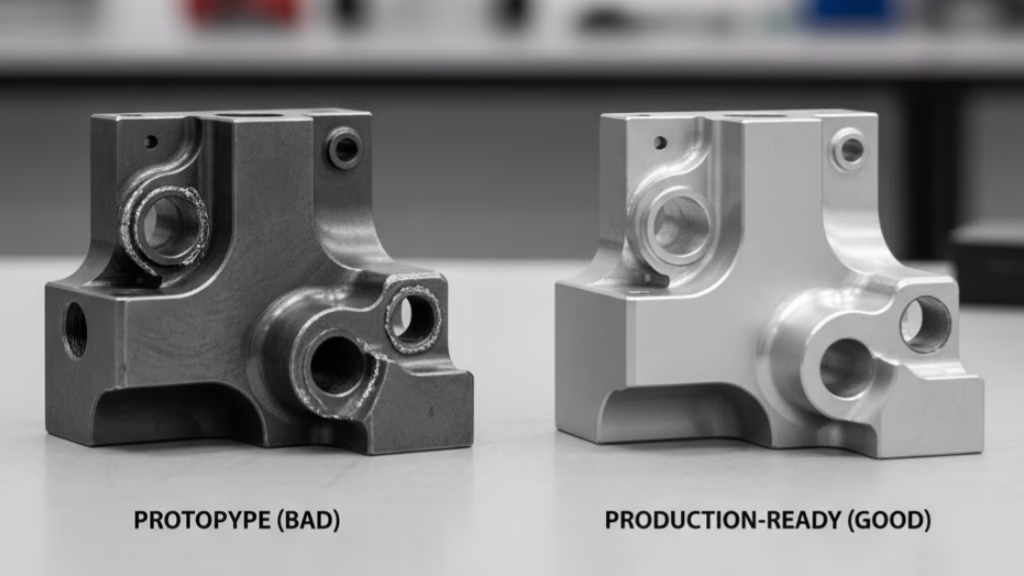
Imaginez deux pièces identiques en aluminium 6061, placées côte à côte. L'une avec un Ra 0,8μm (ou 32 μin) a un aspect propre et mat.
Vous pouvez voir les marques d'outils fines et uniformes de la Processus de fraisage CNCLa surface ainsi créée est homogène et non réfléchissante. Si vous passez le bout de votre doigt dessus, vous pouvez sentir une texture subtile et uniforme, qui témoigne de son origine usinée.
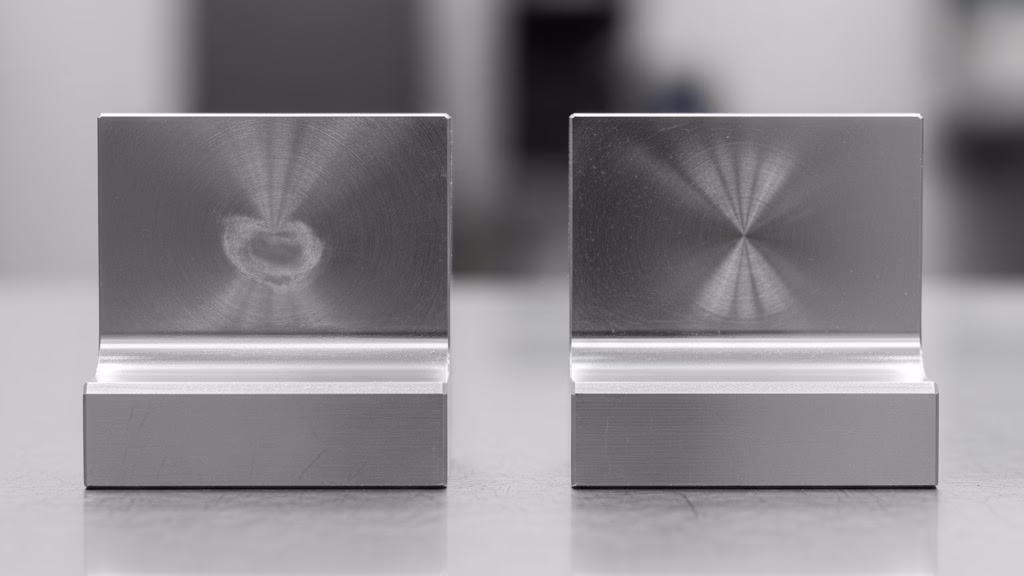
Maintenant, regardez la partie avec un Ra 0,4μm (ou 16 μin) finition. La différence est immédiatement visible. La surface est beaucoup plus réfléchissante, avec une brillance semi-brillante ou satinée. Les marques d'outils sont presque invisibles à l'œil nu.
Au toucher, cette surface est totalement lisse, sans texture perceptible. La différence n'est pas seulement cosmétique ; il s'agit d'un changement fondamental dans la topographie de la surface.
Pour mieux comprendre les implications fonctionnelles, examinons le comportement d'une goutte d'huile sur chaque surface. Sur la surface Ra 0,8μm, l'huile s'étale uniformément mais est retenue dans les vallées microscopiques des marques d'outils. Cette texture peut être bénéfique pour les applications nécessitant une rétention de la lubrification.
Sur la surface Ra 0,4μm, l'huile s'étale plus finement et plus largement, car il y a moins de vallées pour la retenir. Cette propriété est cruciale pour les surfaces qui nécessitent un film fluide cohérent et ininterrompu.
Pourquoi une finition Ra 0,4μm est-elle si chère ?
Voici la question à un million de dollars : pourquoi une modification apparemment minime d'une spécification de finition de surface entraîne-t-elle une augmentation de prix aussi spectaculaire ? La réponse réside dans un changement fondamental du processus de fabrication.
Pour obtenir une finition Ra 0,4μm, il ne suffit pas de faire tourner une machine un peu plus longtemps ; cela nécessite souvent une approche complètement différente, en plusieurs étapes.
Décrivons le parcours d'une pièce dans notre magasin :
- Pour obtenir Ra 0,8μm : Le processus est généralement simple. La pièce est réglée une seule fois sur une machine CNC de haute qualité. Nous utilisons un processus de fraisage ou de tournage finement ajusté, avec des vitesses et des avances optimisées, et un outillage affûté pour obtenir la finition souhaitée en une seule opération. Le processus est efficace et maîtrisé.
- Pour obtenir Ra 0,4μm : Le voyage devient beaucoup plus complexe. Il se présente souvent comme suit :
- Usinage initial : Nous usinons d'abord la pièce à des dimensions proches des dimensions finales, en laissant une petite quantité de matériau sur la surface critique.
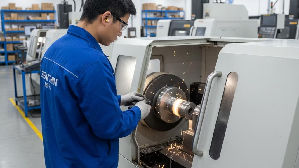
- Opération secondaire : La pièce est ensuite transférée vers une machine complètement différente, une rectifieuse de précision. Cela nécessite une nouvelle configuration, ce qui prend du temps et présente des risques.
- Broyage : Le processus de rectification lui-même est nettement plus lent que le fraisage ou le tournage. La finition supérieure est grâce à un meulage de précisionqui enlève de la matière à l'aide d'une fine meule abrasive.
- Inspection plus stricte : Enfin, la vérification d'une finition Ra 0,4μm nécessite un équipement d'inspection plus sophistiqué et prend plus de temps.
Ce passage d'une opération unique et efficace à un processus en plusieurs étapes est le principal facteur d'augmentation des coûts. Pour mettre les choses en perspective, si nous fixons le coût d'une finition machine standard (Ra 3,2μm) à un niveau de référence de 1.0x, un La finition Ra 0,8μm pourrait coûter de 2,5 à 4,0x. cette ligne de base.
Cependant, le passage à une finition Ra 0,4μm peut faire grimper le coût de 5,0 à 8,0 fois le coût de base initial. Cela signifie qu'en améliorant la finition de Ra 0,8μm à Ra 0,4μm, on peut facilement augmenter le coût de la pièce de 50% à 200%.
Mais le temps de fabrication direct n'explique pas tout. En tant que fournisseur, lorsque nous voyons une exigence de Ra 0,4μm, nous tenons également compte d'un "coefficient de risque."
Le processus en plusieurs étapes augmente les risques d'erreur - un léger défaut d'alignement lors du deuxième réglage ou un problème lors du meulage peut entraîner la mise au rebut de la pièce. Ce risque de taux de rebut plus élevé, qui passe généralement de 2-3% à 8-10%, est subtilement pris en compte dans votre devis.
| Fonctionnalité | Ra 0,8μm (32 μin) | Ra 0,4μm (16 μin) |
|---|---|---|
| Processus de fabrication | Usinage CNC standard de haute précision. | Nécessite une opération de broyage secondaire. |
| Coût relatif | 2,5x - 4,0x la ligne de base. | 5.0x - 8.0x ligne de base. |
| Apparence | Propre, mat, marques d'outils visibles. | Semi-brillant, satiné, les marques d'outils sont pratiquement invisibles. |
| Meilleur pour | Joints statiques, ajustements de roulements, pièces générales de haute qualité. | Joints dynamiques, zones à forte fatigue, composants critiques. |
Faire le bon choix pour votre demande

Maintenant que vous avez compris le "quoi" et le "pourquoi", abordons la question la plus importante : "Quand ?" La décision de spécifier un finition de la surface ne doit jamais être arbitraire ; elle doit être entièrement motivée par la fonction de la pièce.
Insister sur une finition Ra 0,4μm là où elle n'est pas nécessaire est une perte d'argent, mais ne pas la spécifier là où elle est critique peut conduire à l'échec du produit.
Alors, quand une finition Ra 0.4μm est-elle absolument nécessaire ?
- Surfaces d'étanchéité dynamiques : Pour les pièces telles que les tiges hydrauliques ou les arbres rotatifs qui se déplacent contre un joint, une surface lisse de Ra 0,2μm à Ra 0,4μm est essentielle pour éviter les fuites et minimiser l'usure du joint lui-même.
- Zones de stress à haute fatigue : Dans les composants soumis à des charges cycliques élevées, une surface plus lisse peut augmenter de manière significative la durée de vie en fatigue en réduisant les sources de contraintes microscopiques où les fissures peuvent s'amorcer.
- Roulement adapté : Les ajustements de précision pour les roulements nécessitent souvent une finition entre Ra 0,4μm et Ra 0,8μm pour assurer un contact et une répartition de la charge corrects.
Cependant, il est tout aussi important de savoir quand une finition plus lisse est nécessaire. pas mieux. Nous avons travaillé un jour avec un client du secteur des appareils médicaux qui avait spécifié une finition Ra 0,4μm semblable à un miroir sur une bride utilisant un joint en silicone souple pour l'étanchéité statique. Il partait du principe que plus c'est lisse, plus c'est étanche.
Nous leur avons indiqué que pour les joints souples, une surface légèrement plus rugueuse de Ra 0,8μm à Ra 1,6μm offre en effet plus de "grip" et empêche le joint de migrer sous la pression. En adoptant notre suggestion, ils ont non seulement réduit le coût de leurs pièces de 40%, mais ils ont également obtenu un joint plus fiable.
Cela met en évidence un point crucial : la valeur Ra seule ne dit pas tout. Un autre client est venu nous voir avec des arbres rotatifs qui tombaient en panne prématurément, alors que les rapports de qualité de leur ancien fournisseur indiquaient une valeur Ra 0,4μm satisfaisante.
Notre analyse a révélé le problème : la surface avait été obtenue par fraisage à grande vitesse et non par meulage. Une surface fraisée, même avec une faible valeur Ra, présente des marques d'outil directionnelles qui peuvent agir comme une lime contre un joint. Une surface rectifiée présente une texture aléatoire et non directionnelle qui est bien meilleure pour la résistance à l'usure et la lubrification.
Comme l'a souvent écrit l'expert en métrologie George Schuetz de Mitutoyo America Corporation, "L'appel de dessin doit raconter toute l'histoire, sinon vous ne contrôlez pas la fonction de surface, vous ne contrôlez qu'un chiffre".
Pour vous aider à prendre vos décisions, voici un tableau de référence rapide pour les applications courantes :
| Application | Valeur Ra recommandée (μm) |
|---|---|
| Surfaces d'étanchéité dynamiques | 0.2 - 0.4 |
| Zones à forte fatigue | < 0.8 |
| Palier adapté | 0.4 - 0.8 |
| Rainures statiques du joint torique | 0.8 - 1.6 |
| Surfaces générales non critiques | 1.6 - 3.2 |
Vous avez besoin de tolérances plus étroites que celles que le fraisage permet d'obtenir ?
Lorsque votre conception exige des tolérances inférieures au micron et des finitions de type miroir, en particulier sur des matériaux trempés, nos services de rectification CNC constituent la solution ultime. Nous veillons à ce que vos composants les plus critiques répondent aux spécifications les plus strictes.
Secrets de DFM que votre fournisseur connaît
Au-delà des coûts directs et des applications fonctionnelles, il existe plusieurs Conception pour la fabrication (DFM) des pièges qui peuvent gonfler inutilement le coût de vos pièces. Un bon partenaire de fabrication vous aidera à repérer ces problèmes, mais le fait d'en être conscient vous-même vous place dans une position beaucoup plus forte.
L'un des pièges les plus courants consiste à spécifier une finition de haute précision sur une caractéristique difficile ou impossible à atteindre. Nous avons un jour reçu un dessin pour une pièce complexe à 5 axes qui demandait une finition Ra 0,4μm au fond d'un canal interne étroit et profond.
Bien que le modèle CAO soit parfait, en réalité, aucun outil de meulage standard ne pouvait accéder à cette zone. Le seul moyen d'y parvenir aurait été de recourir à un processus d'électroérosion hautement spécialisé et personnalisé, ce qui aurait augmenté le coût de la pièce de plus de 150%.
En travaillant avec l'équipe d'ingénieurs du client, nous avons confirmé que la finition n'était pas essentielle pour la fonction et qu'une finition mécanique standard était acceptable, ce qui a évité au projet des dépenses inutiles.
Un autre piège subtil mais critique consiste à ne pas spécifier le processus de fabrication. processus, juste le résultat. Comme nous l'avons évoqué avec le cas de la défaillance de l'arbre, une finition Ra 0,4μm obtenue par fraisage est fonctionnellement différente de celle obtenue par meulage.
La première crée des pics et des vallées directionnels, tandis que la seconde crée une surface aléatoire, en plateau, plus propice à l'usure et à la lubrification.
Si la fonction de votre pièce dépend de ce caractère de surface spécifique, une simple note sur votre dessin peut vous éviter de futurs maux de tête liés à l'analyse des défaillances.
Une note comme, "La surface doit être finie à Ra 0,4μm. LE PROCESSUS FINAL DOIT ÊTRE LA RECTIFICATION". lève toute ambiguïté et garantit que vous obtiendrez les performances fonctionnelles que vous attendez.
Enfin, n'oubliez pas que le choix du matériau joue un rôle important. Il est beaucoup plus facile et moins coûteux d'obtenir une finition soignée sur un matériau tendre comme l'aluminium que sur un matériau plus dur comme l'acier. acier à outils trempé ou alliages exotiques comme l'Inconel. Tenez toujours compte des propriétés du matériau lorsque vous définissez vos exigences en matière de finition de surface.

Un cadre décisionnel en trois étapes et une liste de contrôle DFM
La connaissance est puissante, mais seulement lorsqu'elle est exploitable. Pour vous aider à traduire ces connaissances dans votre travail quotidien, voici un cadre simple en trois étapes pour prendre des décisions en matière de finition de surface, ainsi qu'une liste de contrôle DFM finale à passer en revue avant de signer un dessin.
Le cadre décisionnel en 3 étapes
- Évaluer la fonctionnalité : Avant toute chose, posez-vous la question : Quelle est la fonction première de cette surface ? S'agit-il d'un joint dynamique ou statique ? S'agit-il d'une surface d'appui ? Est-elle soumise à une fatigue importante ? Ou s'agit-il simplement d'une surface de dégagement ? Votre réponse est le facteur le plus important.
- Explorer les alternatives : Si une finition de haute précision semble nécessaire, prenez le temps de remettre en question cette hypothèse. Un changement de matériau, un autre type de joint ou l'ajout d'une douille trempée pourraient-ils éliminer la nécessité d'une finition coûteuse sur un composant complexe et de grande taille ?
- Appliquer localement : Une fois que vous avez confirmé qu'une finition fine est nécessaire, appliquez-la seulement à la zone fonctionnellement critique. Il n'est pas nécessaire de spécifier une finition Ra 0,4μm sur l'ensemble d'une pièce si seule une petite partie de celle-ci effectue le travail critique. Utilisez des repères locaux sur votre dessin pour isoler ces zones de haute précision.
Votre liste de contrôle DFM ultime
Avant de publier votre prochain dessin, passez en revue cette liste de contrôle rapide :
- [ ] Nécessité : Cette spécification relative à l'état de surface répond-elle vraiment à une exigence fonctionnelle, ou est-elle basée sur un ancien dessin ou une hypothèse conservatrice ?
- [ ] Accessibilité : Un outil standard (fraise, meule) peut-il réellement atteindre la surface que j'ai spécifiée ?
- [ ] Processus : Pour les surfaces critiques sur le plan dynamique ou sensibles à la fatigue, ai-je envisagé de spécifier le processus de fabrication final (par exemple, "Doit être rectifié") en plus de la valeur Ra ?
- [ ] Localisation : Ai-je limité l'appel à la finition fine à la plus petite zone fonctionnelle possible ?
Devenir un ingénieur qui comprend la fabrication
La capacité à spécifier intelligemment une finition de surface est la marque d'un véritable grand ingénieur. Elle témoigne d'une compréhension profonde qui va au-delà de la théorie pure de la conception et s'inscrit dans les réalités pratiques et financières de la fabrication.
Faire le bon choix entre Ra 0,8μm vs. Ra 0,4μm en Usinage CNC ne consiste pas seulement à économiser de l'argent, mais aussi à créer un design optimisé, fiable et élégant.
Chez Zenithin, nous nous considérons comme plus qu'un simple atelier d'usinage qui exécute vos dessins. Nous sommes votre partenaire de fabrication, prêt à collaborer avec vous pour trouver l'équilibre parfait entre performance et coût.
Êtes-vous confronté à un défi similaire dans le cadre de votre prochain projet ? Vous ne savez pas si vos tolérances et vos finitions sont optimisées ?
Téléchargez votre dessin dès aujourd'hui pour obtenir un avis gratuit d'un expert. Analyse DFM et un devis précis de notre équipe d'ingénieurs. Construisons ensemble quelque chose de grand.
Références et notes
[1] Rugosité de surface moyenne (Ra) : Ra est la moyenne arithmétique des valeurs absolues des écarts de hauteur de profil par rapport à la ligne moyenne. Il s'agit d'un paramètre clé défini dans la norme ASME Y14.36 pour les symboles de texture de surface.
[2] Conception pour la fabrication (DFM) : Il s'agit d'une pratique d'ingénierie qui consiste à concevoir des produits de manière à ce qu'ils soient faciles à fabriquer. L'objectif est de réduire les coûts de fabrication et les problèmes potentiels. Pour en savoir plus sur ce sujet, consultez ce guide complet sur la DFM pour l'usinage CNC.