Ne laissez plus des dessins techniques ambigus grever le budget de votre projet et créer des frictions entre vos équipes. Il s'agit du guide définitif permettant aux responsables d'exploiter le dimensionnement et le tolérancement géométriques (GD&T) en tant qu'outil commercial puissant. Vous obtiendrez les données et les cadres exacts pour réduire les coûts et améliorer la qualité, dès aujourd'hui.
Le dimensionnement et le tolérancement géométrique (GD&T) est un langage d'ingénierie symbolique utilisé sur les dessins techniques pour définir et communiquer avec précision l'intention fonctionnelle d'une pièce. Contrairement au tolérancement +/- traditionnel, il contrôle la forme, l'orientation et l'emplacement des caractéristiques, garantissant que les pièces s'adaptent et fonctionnent correctement, ce qui peut augmenter la tolérance de fabrication de plus de 50%.
Maintenant que vous connaissez les bases, je vais vous montrer les études de cas réels et les données exploitables dont vous avez besoin pour faire de la GD&T la compétence la plus rentable de votre équipe.
Redéfinir la GD&T : Plus qu'un outil de dessin

Recadrons votre vision des choses Dimensionnement et tolérancement géométriques. Pendant trop longtemps, il a été considéré comme un ensemble complexe de symboles que seuls les ingénieurs concepteurs devaient maîtriser. Il s'agit là de l'idée fausse la plus répandue, et c'est là que la plupart des entreprises échouent.
La GD&T n'est pas une technique de dessin isolée ; c'est un outil commercial puissant déguisé en langage technique.
Un dessin GD&T n'est pas un croquis, mais un schéma précis. contrat technique. C'est le langage universel qui permet enfin à vos services de conception, de fabrication et de qualité de parler le même dialecte.
Alors qu'un dessin traditionnel de tolérance plus/moins laisse place à l'interprétation et au débat, un dessin GD&T est sans ambiguïté. Il traduit une intention de conception abstraite, telle que "cette surface doit être plane pour assurer un scellement correct", en une instruction claire, mesurable et juridiquement contraignante que tout le monde peut comprendre et exécuter.
Comme l'a souligné Alex Krulikowski, ancien membre de l'équipe de l Comité ASME Y14.5Comme l'explique le directeur général de la DGT, "lorsque la GD&T est utilisée, la description de la pièce est précise et ne laisse aucune place à l'interprétation. Cela élimine l'ambiguïté... et garantit que l'intention du concepteur est clairement communiquée".
Cependant, le simple fait d'envoyer votre équipe à un cours de formation ne résout pas automatiquement le problème. En réalité, il s'agit du début d'un parcours. L'expérience montre que les entreprises se situent généralement dans l'un des trois niveaux de maturité GD&T :
- Niveau "décoratif" : Les ingénieurs saupoudrent quelques symboles GD&T sur les dessins pour paraître professionnels, mais les équipes de fabrication et d'inspection les ignorent ou ne les comprennent pas. Cela crée un faux sentiment de sécurité.
- Niveau "isolé" : Votre équipe de conception devient très compétente, créant des dessins de niveau expert. Cependant, elle travaille en vase clos. L'équipe de fabrication ne dispose pas des processus et l'équipe de qualité n'a pas les programmes CMM ou les jauges nécessaires pour valider la conception. Il en résulte des frictions internes, les concepteurs étant considérés comme créant des pièces "impossibles".
- Niveau "collaboratif" : Tel est l'objectif. Dans ce cas, la GD&T sert de langage commun dans le cadre d'une révision obligatoire entre les différents services avant la publication d'un dessin. Il s'agit d'une philosophie dans laquelle la conception, la fabrication et la qualité négocient ensemble le dessin, en veillant à ce que la fonctionnalité, la fabricabilité et l'inspectabilité soient intégrées dès le départ.
Votre rôle en tant que manager n'est pas seulement d'approuver la formation, mais de diagnostiquer le niveau auquel se trouve votre organisation et de promouvoir le changement culturel nécessaire pour atteindre le stade de la collaboration.
Construire votre rapport sur le retour sur investissement avec des données et de l'autorité
Pour défendre un changement tel que la mise en œuvre Dimensionnement et tolérancement géométriquesPour cela, vous avez besoin de plus qu'un simple argument technique - vous avez besoin d'une analyse de rentabilité. Lorsque vous proposez d'investir dans la formation GD&T et dans des changements de processus, on vous demandera le retour sur investissement. Voici les données nécessaires à l'élaboration de ce rapport.
Les avantages financiers ne sont pas abstraits, ils sont mesurables. Voici quelques chiffres validés par l'industrie :
| Niveau de maturité | Défi primaire | Impact sur les entreprises | Action du directeur |
|---|---|---|---|
| Décoratif | Symboles incompris ou ignorés | Faux sentiment de sécurité, échecs inattendus | Obliger à une formation de base |
| Isolé | La conception fonctionne en vase clos | Frottement interne élevé, pièces "impossibles". | Investir dans des outils de fabrication/qualité |
| Collaboratif | Obtenir l'adhésion de tous les services | Réduction des coûts, amélioration de la qualité, accélération du TTM | Instaurer des examens obligatoires de la conception |
Il ne s'agit pas de dépenser plus pour être plus précis, mais de dépenser plus intelligemment.
Comme l'indique James D. Meadows, consultant industriel et auteur, "les mauvaises pratiques en matière de tolérancement constituent une perte cachée pour les bénéfices des entreprises. Elles entraînent des rebuts, des retouches, des problèmes d'assemblage et des débats interminables entre les services. La GD&T correctement appliquée n'est pas une dépense ; c'est un outil d'évitement des coûts.
L'outil financier le plus puissant de la GD&T est peut-être le concept de Tolérance de bonusLa condition matérielle maximale est débloquée en appliquant le modificateur de condition matérielle maximale (MMC). La logique est simple :
Tolérance réelle disponible = Tolérance géométrique spécifiée + Tolérance de bonification
Cette formule représente une approche dynamique et intelligente du tolérancement. Il indique à votre équipe de fabrication que tant qu'elle produit une caractéristique éloignée de sa taille la plus dangereuse et la plus ajustée, le système se met automatiquement en place. récompenses les doter d'une tolérance supplémentaire.
Ce mécanisme garantit mathématiquement l'interchangeabilité des 100% tout en offrant à votre atelier de production la plus grande flexibilité possible, convertissant directement l'intelligence technique en économies tangibles.
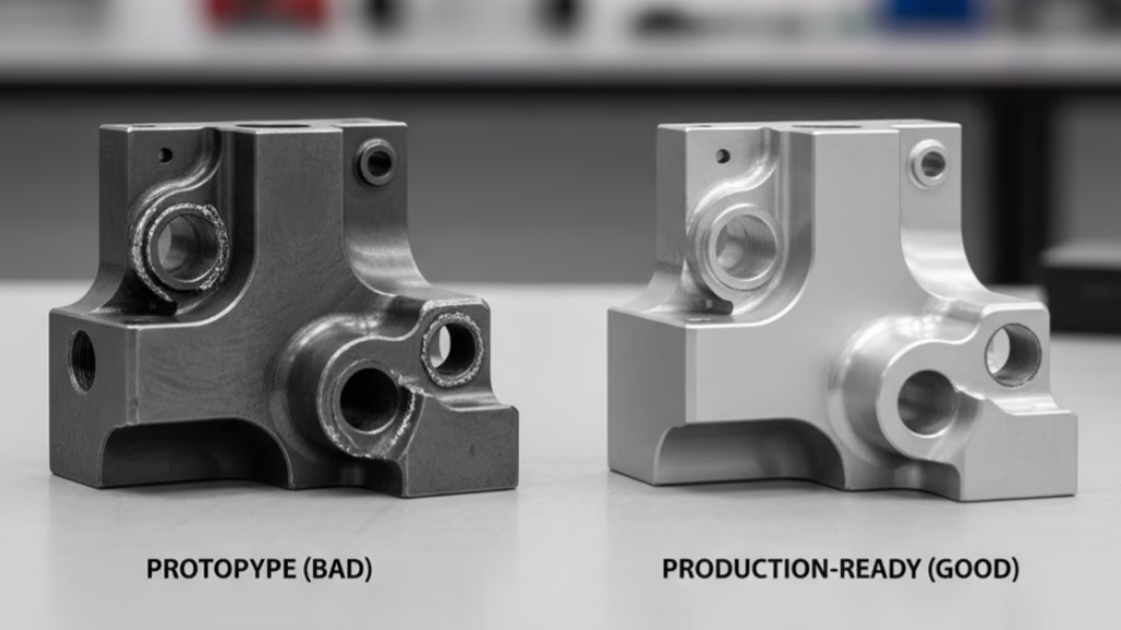
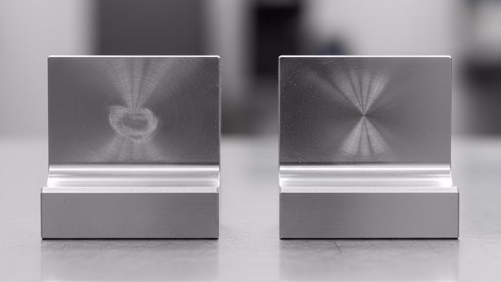
Corrigez les erreurs coûteuses de vos dessins de tolérance
Vous en avez assez des dessins qui entraînent des rebuts et des retouches ? Notre guide DfM fournit un cadre éprouvé pour éliminer l'ambiguïté et garantir que votre intention de conception est parfaitement fabriquée. Arrêtez le cycle des erreurs coûteuses.
3 Concepts GD&T que les managers doivent maîtriser

Il n'est pas nécessaire de devenir un expert technique pour chaque symbole, mais pour diriger efficacement votre équipe, vous devez saisir l'importance stratégique de trois éléments fondamentaux. Dimensionnement et tolérancement géométriques concepts.
En les comprenant, vous pourrez poser les bonnes questions lors des revues de conception et guider votre équipe vers des solutions plus intelligentes et plus rentables, proposées par une entreprise de confiance. Usinage CNC partenaire.
1. Les points de référence : Le point d'ancrage de votre projet
Oubliez la définition technique. Pensez à Références en tant que ancre de votre pièce. Elles définissent la position de la pièce dans l'assemblage et constituent le point d'origine de toutes les mesures. Tout est mesuré par rapport à eux.
La règle la plus importante est que vos points de référence doivent simuler la façon dont la pièce fonctionne réellement et s'adapte à ses pièces d'accouplement. Cette règle n'est pas négociable.
J'ai vu un jour un projet dans lequel une équipe, pour des raisons de commodité de dessin, avait choisi trois surfaces parfaitement planes et accessibles comme points de référence. Des millions ont été dépensés en moules et en outillage sur la base de ce dessin. À la fin du projet, on a découvert que les véritables caractéristiques de localisation de la pièce dans l'assemblage final étaient complètement différentes.
L'ensemble de la chaîne de tolérance était fondamentalement défectueux. Ce choix "pratique" a entraîné une série catastrophique de modifications de la conception et de l'outillage, qui ont coûté cher à l'entreprise.
En tant que responsable, la question la plus importante que vous puissiez poser lors d'une revue de conception est la suivante : "Ces points de référence reflètent-ils parfaitement le fonctionnement de cette pièce dans le monde réel ?"
2. Le cadre de contrôle des fonctionnalités : Une commande structurée
Le cadre de contrôle des fonctionnalités est une boîte rectangulaire remplie de symboles. Ne vous y perdez pas. Prenez-le plutôt pour ce qu'il est : une commande parfaitement structurée. C'est une phrase qui ne laisse aucune place à l'erreur d'interprétation.
Il répond à quatre questions dans un ordre clair et logique :
- Quelle caractéristique contrôlons-nous ?
- Quel type de contrôle appliquons-nous (par exemple, position, planéité, perpendicularité) ?
- Comment serrer la contrôlons-nous (la valeur de tolérance) ?
- Par rapport à quoi le contrôlons-nous (les bases de données) ?
En apprenant à votre équipe à considérer ce cadre comme un ordre clair plutôt que comme un code complexe, vous favorisez une culture de la précision et de la clarté.
3. Condition matérielle maximale (MMC) : La tolérance intelligente
Il s'agit sans doute du concept de réduction des coûts le plus puissant de toute l'économie européenne. Dimensionnement et tolérancement géométriques. Condition matérielle maximale (MMC)représentée par le symbole Ⓜ, vous permet de passer d'une tolérance rigide et fixe à une tolérance intelligente et flexible.
Elle s'applique à des caractéristiques telles que les trous et les goupilles pour lesquels le jeu est important. En fait, elle crée un scénario gagnant-gagnant : elle indique au concepteur de spécifier la tolérance nécessaire pour le scénario le plus défavorable (lorsque l'axe est le plus grand et que le trou est le plus petit).
Il indique ensuite au fabricant que pour chaque bit qui s'éloigne de la taille la plus défavorable, il bénéficie d'une "tolérance bonus" égale pour l'emplacement de la caractéristique.
Cela permet une plus grande variation dans la fabrication sans jamais compromettre la capacité de la pièce à être assemblée. Ce niveau de précision est constamment grâce au fraisage CNC de précision.
Il s'agit d'un excellent compromis qui permet de réduire les coûts et les déchets, tout en garantissant la fonctionnalité.
Feuille de route de votre équipe pour la mise en œuvre de la GD&T
Vous êtes convaincu de sa valeur, mais la question la plus importante se pose maintenant : "Que dois-je faire demain matin ?" Un tel changement peut sembler insurmontable, mais ce n'est pas une fatalité.
Au lieu de procéder à une refonte radicale, vous pouvez mettre en œuvre les mesures suivantes Dimensionnement et tolérancement géométriques par le biais d'une approche structurée et progressive. Voici une feuille de route pratique pour guider la transformation de votre équipe.
Il ne s'agit pas seulement de former, mais de construire une capacité durable. Suivez ce plan en trois étapes pour faire passer votre équipe des connaissances de base à l'intégration complète.
1. Unifier le "pourquoi"
Avant d'enseigner le "comment", tout le monde doit comprendre le "pourquoi". La première chose à faire est d'obtenir l'adhésion de toutes les parties prenantes. Organisez une réunion de lancement avec des représentants de la conception, de la fabrication et de la qualité. Au cours de cette séance, présentez l'analyse de rentabilité.
Utilisez les données de ce guide : présentez les études de cas, le potentiel d'un projet d'éducation à l'environnement et de développement durable, et le potentiel d'un projet d'éducation à l'environnement. 57% gain de toléranceet le coût important de la Ordres de modification de l'ingénierie. L'objectif est de faire en sorte que la GD&T ne soit plus perçue comme un "problème de conception" mais comme une "solution commerciale à l'échelle de l'entreprise".
2. Donner des moyens d'action avec le "Quoi" et le "Comment"
Une fois l'équipe alignée, il faut lui fournir les outils nécessaires à sa réussite. Cela passe par une formation standardisée et fondamentale. Veillez à ce que tout le monde, et pas seulement les concepteurs, reçoive la même formation de base sur les principes et symboles GD&T fondamentaux.
Complétez cela par des ressources accessibles, telles que la création d'une bibliothèque numérique partagée avec des tableaux de référence rapide pour les symboles les plus courants et l'établissement d'une "micro-norme" interne simple pour les caractéristiques communes afin d'assurer la cohérence de tous les dessins.
3. Le prouver par un projet pilote
La théorie est une chose, la pratique en est une autre. Choisissez un projet à faible risque, non critique, qui servira de projet pilote. L'équipe dispose ainsi d'un espace sûr pour appliquer ses nouvelles compétences, faire des erreurs et apprendre sans mettre en péril une échéance importante.
Désignez un champion de la GD&T ou faites appel à un expert pour vous guider au cours de cette phase. Par la suite, procédez à un bilan complet pour célébrer les réussites et documenter les leçons apprises. Ce projet pilote deviendra votre succès interne et le modèle de la future mise en œuvre.
Enfin, pour démontrer le succès de votre initiative, vous devez la mesurer. Suivez les indicateurs clés de performance (ICP) qui reflètent directement l'impact de la GD&T, tels que la réduction des ECO liés à la conception, la diminution des questions posées par l'atelier sur l'interprétation des dessins et l'augmentation du rendement des assemblages au premier passage.
Ces mesures fourniront les données concrètes nécessaires pour mettre en évidence votre leadership et le succès tangible du programme.
Conclusion : La GD&T est votre ticket d'entrée pour la fabrication intelligente
Les avantages de l'adoption Dimensionnement et tolérancement géométriques-La réduction des frictions, la diminution des coûts et l'amélioration de la qualité sont des raisons suffisamment convaincantes en elles-mêmes. Cependant, la raison la plus importante de l'adopter aujourd'hui n'a pas grand-chose à voir avec l'amélioration de vos dessins 2D actuels. Il s'agit d'assurer l'avenir de votre entreprise dans un monde de plus en plus numérique.
Nous sommes à l'aube de la prochaine révolution industrielle. L'époque où l'on s'appuyait uniquement sur des dessins en 2D sur papier est révolue. L'avenir est Définition basée sur un modèle (MBD)où le modèle 3D est la seule source de vérité, contenant toutes les informations relatives au produit et à la fabrication (PMI) nécessaires à la construction d'une pièce. Dans ce nouveau paradigme, la GD&T est l'élément le plus important. syntaxe du fil numérique.
Réfléchissez à ce que cela signifie :
- Vos machines d'inspection CMM ne nécessiteront plus des heures de programmation manuelle ; elles généreront automatiquement des trajectoires d'inspection en lisant les informations GD&T directement à partir du modèle 3D.
- Vos machines à commande numérique exploiteront ces données pour la compensation automatisée des parcours d'outils.
- Votre logiciel de simulation exécutera des assemblages virtuels en utilisant ces informations précises sur les tolérances, prévoyant les problèmes d'ajustement avant qu'une seule pièce de métal ne soit coupée.
L'investissement d'aujourd'hui dans le dimensionnement et le tolérancement géométriques (GD&T) est l'acompte sur le billet d'entrée de votre entreprise dans l'industrie 4.0. Alors que vos concurrents en sont encore à débattre de la signification d'un symbole sur un dessin imprimé, votre organisation fonctionnera sur un fil numérique continu, de la conception à l'inspection.
Ce n'est pas seulement une question d'efficacité, c'est une question de pertinence et de survie. La décision stratégique que vous prenez aujourd'hui déterminera si votre entreprise mène la charge ou si elle est laissée pour compte.
Références et notes
[1] Norme ASME Y14.5 : Il s'agit de la norme officielle pour le dimensionnement et le tolérancement géométriques publiée par l'American Society of Mechanical Engineers (ASME). Il s'agit de la ligne directrice faisant autorité pour le langage de conception de la GD&T aux États-Unis.
[2] Tolérance de bonification : Tolérance supplémentaire pour un contrôle géométrique qui est autorisée lorsqu'une caractéristique de taille s'écarte de son état matériel maximal (MMC) ou de son état matériel minimal (LMC). Ce concept est un avantage clé de la GD&T pour augmenter la fabricabilité.