Stop designing thin-walled parts that warp, fail inspection, or cause budget overruns. This definitive guide provides the actionable DFM rules, material selection insights, and advanced machining strategies you need. We’ll show you how to master the “impossible triangle” and finally balance strength, precision, and machinability.
Balancing strength, precision, and machinability in thin-wall design requires a 3-part strategy. First, use Design for Manufacturability (DFM) principles like ribs, fillets, and optimal height-to-thickness ratios to maximize rigidity. Second, select low-stress materials (like 6061-T651 or cast tooling plate) to prevent warping. Finally, implement multi-stage machining processes that include stress-relief steps.
But there’s a catch: 70% of part failure comes from a single source most engineers completely ignore.
Dive in to learn the specific DFM rules, material data charts, and expert-level strategies that will stop thin-wall failures before they start.
The Foundation of Balance
Here’s the first “aha!” moment, and it’s a big one: For most thin-walled parts, the final, catastrophic deformation isn’t just from the force of the cutting tool.
We call it the “70/30 Rule”.
Based on our experience, roughly 70% of part warping comes from releasing the internal residual stress locked inside the raw material, while only about 30% comes from the cutting forces or heat of the machining process itself.
What does this mean for you? It means your battle is won or lost antes de a single chip flies. As the designer, you are already determining 70% of the part’s success or failure in your CAD software and on your material spec sheet.
This shifts your entire objective. The goal should not be to design a part with just high strength. The goal must be to design a part with high rigidity y low internal stress.
Let’s talk about rigidity. The stiffness of your part is exponentially more powerful than you might think. The formula for a simple beam’s stiffness ($k$) is proportional to its thickness ($t$) cubed ($k \propto t^3$).
This cubic relationship is your secret weapon.
- If you increase a wall’s thickness by just 10% (say, from 1.0mm to 1.1mm), you increase its stiffness by 33% ($1.1^3 = 1.331$).
- That tiny 0.1mm you add in a critical area might doble the part’s rigidity (depending on the base thickness), making it far more stable during machining than if you had simply chosen a more expensive, “stronger” alloy.
[Pillar 1: DFM] Avoiding 80% of Manufacturing Costs in Your CAD
As Dr. David M. Anderson, a leader in Design for Manufacturability (DFM), points out, “by the time a design is released to manufacturing, 80 percent of its cost is already locked in.” For thin-walled parts, this number might be even higher.
Your CAD software is your most powerful—and most dangerous—tool. This is where you prevent failures. But this is also where a critical blind spot can trap you.
The “FEA Fallacy”
Let’s talk about that blind spot: your Finite Element Analysis (FEA) simulation. You’ve run your analysis, and it confirms the part will easily withstand its final use-case load of 100N. It looks perfect.
Here’s the problem: Your FEA is likely lying to you.
That part will never experiencia its use-case load if it fails during manufacturing. The forces it endures during machining—the side-load from an end mill, the crushing pressure from a vise—can be far greater and more dynamic.
Your FEA must simulate the “manufacturing state,” not just the “application state.” Ask your FEA:
- What happens when a 150N cutting force hits the top of this wall?
- Does it deflect 0.1mm, instantly violating your 0.05mm tolerance?
- What happens when a clamp applies 2000N of pressure? Does the part bow antes de the tool even touches it?
If you don’t simulate the manufacturing process, your analysis is incomplete.
Your Actionable DFM Checklist
Use these rules to ensure your design is manufacturable from the start.
Respect the “Golden Rule”:
The H:T RatioThe Wall Height-to-Thickness (H:T) Ratio is the single most important number in your design. It dictates cost, risk, and feasibility. We have a complete Proven CNC Wall Thickness Guide, but the basics are:
-
- < 10:1 (Safe Zone): Easily machined. Low risk.
- 10:1 to 20:1 (Challenging Zone): Requires experienced machinists and specific strategies. Costs begin to rise.
- 20:1 to 30:1 (Expert Zone): This is specialist territory. It requires 5-axis machines, advanced tooling, and vibration control. Expect costs to increase significantly.
- > 30:1 (High-Risk Zone): Avoid this at all costs. The yield rate plummets, and costs become exponential. If your design is here, you must reconsider the entire concept.
Build “Geometric” Stiffness
Don’t just add mass; add shape. Use ribs and gussets to dramatically increase stiffness with minimal material addition. A well-placed rib can have a greater impact on rigidity than doubling the wall thickness.
And always, always use fillets (internal radii) at the base of thin walls. Sharp corners are stress concentration points; a smooth radius distributes load and dramatically improves the tool’s ability to create a clean path.
Design for Workholding
Stop and ask the most important question: “How will the machinist hold this thing?”
-
- Can you add temporary “sacrificial material”—a solid frame or specific lugs—that the machinist can safely clamp?
- Can you add tooling holes for bolts or alignment pins?
- This “sacrificial” material, which is machined away in the final operation, is often the key to achieving stability for the high-precision finishing passes.
Avoid the “Monolithic Trap”
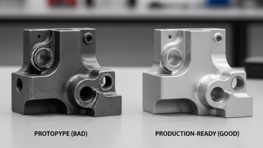
Engineers often chase the “monolithic design”—milling a complex part from a single, solid block of metal. It seems strong and elegant.
In reality, it’s often a trap. It creates deep pockets, extreme H:T ratios, massive material waste, and unleashes 100% of the material’s internal stress.Ask yourself: Could this “impossible” part be broken into two or three simple parts that are easily machined and then joined by laser welding o structural bonding?
The assembled solution is often cheaper, faster, and more dimensionally stable than the monolithic “masterpiece.”
Struggling with DFM for a Complex Part?
Thin walls, deep pockets, and complex geometries are our specialty. Before you lock in a design that’s costly to produce, let our engineers provide a free DFM analysis to optimize your part for cost and manufacturability.
[Pillar 2: Material] Choose “Stability” Over “Strength”
The “memory” of your material often matters more than its “grade.”
This is the key to solving that 70% internal stress problem we talked about. When a material like aluminum or titanium is formed at the mill—by being rolled flat or extruded through a die—it’s like compressing a powerful spring. That energy, that “memory,” is locked deep inside the material’s grain structure.
When your machinist starts cutting away 90% of that material to create your thin-walled part, you are essentially “releasing” that spring. The material expands, twists, and warps, all on its own.
Your job as the designer is to choose a material with “amnesia.”
The Truth About Aluminum
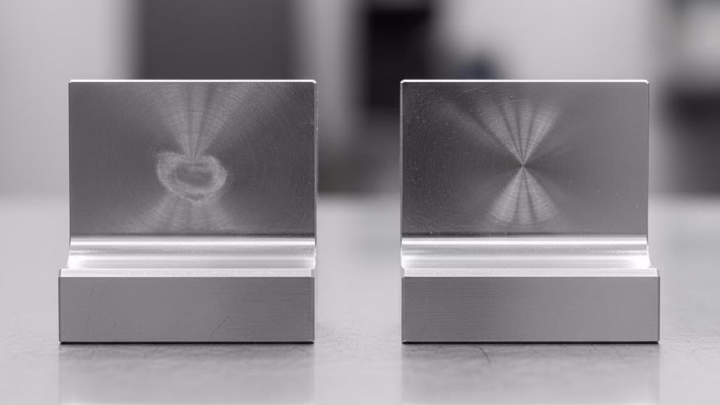
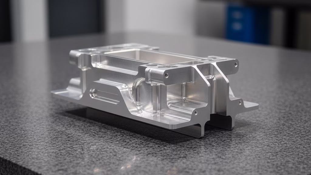
Let’s look at a real-world example. We had a client design a large, 400mm x 400mm optical mounting plate. It was thin and needed to be perfectly flat, with a flatness tolerance of just 0.05mm. The drawing simply specified “Aluminum 6061-T6.”
We machined the first one from a standard T6 rolled plate. After milling the pockets, the part came off the machine looking like a potato chip—it had bowed by 0.7mm, completely destroying the flatness tolerance. This wasn’t a machining error; it was the material releasing its internal stress.
Here is the hierarchy you should use:
- High Risk (6061-T6): This is the standard, rolled-plate aluminum. It is packed with internal stress and is a nightmare for precision, thin-walled parts.
- Recommended (6061-T651): The “T651” is the critical part. This temper means the material has been stretched at the mill specifically to relieve the majority of that internal stress. It is far more stable than T6. Your drawing debe specify T651.
- Expert’s Choice (MIC-6 / ATP-5): This is our “secret weapon.” These are cast tooling plates. Because they are cast (poured) rather than rolled, they have virtually zero internal stress. Their raw strength is slightly lower than 6061, but their stability is unmatched. For that warped optical plate? We switched to MIC-6, and the next part came off the machine with a flatness of 0.03mm. Problem solved.
If your part’s primary function is precision and stability (like a manifold, jig, or optical base), and not pure strength, a cast tooling plate is the superior choice.
Stainless Steel and Titanium
This “stress memory” exists in other materials, too.
- 304 Stainless Steel: This is a difficult material for thin walls. It has poor thermal conductivity (the heat from cutting doesn’t escape) and it work-hardens, meaning it gets harder as you cut it. This increases cutting forces and leads to vibration and chatter. See our full 303 vs. 304 vs. 316 guide for more.
- 17-4PH Stainless: A much better choice. It can be heat-treated after machining to achieve excellent strength, allowing it to be machined in a softer, more stable state.
- Titanium (Ti-6Al-4V): This is the ultimate material for strength-to-weight and has a very low coefficient of thermal expansion (CTE), making it dimensionally stable against temperature changes. However, it generates high machining stress. For a thin-walled titanium part, a multi-stage process of roughing, stress-relief heat treatment, and finishing isn’t just a good idea—it is mandatory. Check out our guide to machining titanium alloys for more detail.
Key Material Trade-Offs
Key Material Properties for Thin-Wall Stability
| Material | Internal Stress | Machinability | Característica principal |
|---|---|---|---|
| 6061-T6 | Alta | Bien | Common (Use T651 instead!) |
| 6061-T651 | Bajo | Bien | Best all-around choice |
| MIC-6 / ATP-5 | Near-Zero | Excelente | Ultimate stability (lower strength) |
| 304 SS | Medio | Pobre | Work-hardens; high vibration risk |
| 17-4PH SS | Medio | Fair | Heat-treatable for high strength |
| Ti-6Al-4V | Alta | Very Poor | Best strength-to-weight; low CTE |
[Pillar 3: Machining] The “Black Box” Engineers Must Understand
Have you ever sent a part out for quote and received three completely different prices? One quote might be 3x higher than another. The lowest quote isn’t just cheaper; it often comes with an impossibly short lead time.
This is a red flag. The price difference doesn’t reflect the pieza; it reflects the proceso.
You are looking at the difference between a supplier who understands “process integrity” and one who is taking a shortcut that is guaranteed to fail. As an engineer, you must understand what’s inside this “black box” of machining, because the right process is the only thing that can protect your design’s strength and precision.
Strategy 1: The “Onion Peel” Strategy
You can’t machine a thin-walled part in one go. It has to be “peeled” like an onion to carefully manage the stress release. The cheapest, fastest supplier will try to machine your part in one operation. This is what we call the “cheapest quote fallacy.”
We saw this firsthand with a medical device team designing a complex titanium implant. They chose a supplier who was 40% cheaper and promised a 3-week lead time. That supplier tried to machine the part in one shot. The result? 45 of the 50 parts warped uncontrollably from stress release, and the entire batch was scrapped.
Our 6-week, higher-cost process included four distinct stages:
- Roughing: Machine away the bulk of the material, “releasing” 80% of the internal stress.
- Stress Relief: A critical, non-machining step. The part is un-clamped and put through a heat treatment or aging cycle to normalize and relax.
- Semi-Finishing: Re-clamp the now-stable part and machine it closer to the final shape.
- Acabado: The final, light-pass machining to hit your critical tolerances.
That “expensive” 4-stage process is, in fact, the sólo way to get a usable part. It delivers the lowest Total Cost of Ownership (TCO) because it actually works. When you see a high quote with a longer lead time, it’s often a sign that the supplier actually knows how to make your part.
Strategy 2: The Art of Workholding
The second challenge is how to hold the part. A standard machinist’s vise is designed to grip with immense force. If you put your thin-walled part in a vise, you will crush or distort it antes de a tool even touches it. The part will be machined “perfectly” in its stressed state, and then “spring back” into a non-conforming shape the moment it’s released.
A specialist must use advanced workholding:
- Custom Soft Jaws: Jaws machined to perfectly match the part’s profile, distributing clamping pressure evenly.
- Vacuum Chucks: Sucks the part flat against a fixture plate, providing excellent stability with zero clamping stress.
- Adhesive/Bonding: For the most delicate parts, they may be temporarily bonded to a sub-plate for machining.
Strategy 3: The Magic of Toolpaths (HSM)
Finally, how the material is cut is critical. The old method of “heavy cuts” is a disaster for thin walls. It induces massive tool pressure, heat, and vibration.
The modern solution is High-Speed Machining (HSM). As machining dynamics expert Dr. Scott Smith explains, the instinct to “go slow” is often wrong. The real solution is “a ‘light-and-fast’ approach… [This] minimizes tool engagement time and cutting forces, removing material quickly without pushing the part.”
This is often done with fresado trocoidal toolpaths. Instead of plowing a tool straight through the material, this path uses a “looping” or “sweeping” motion. It takes very light, very fast cuts, turning solid metal into chips with almost no heat, vibration, or force. This is what allows a machinist to cut a 30:1 wall ratio without causing it to sing like a guitar string and deflecting it out of tolerance.
Conclusion: From “Engineer” to “System Balancer”
You see, a perfect thin-walled part isn’t just “designed” by you or “manufactured” by a machinist. It is “balanced” into existence through a systematic partnership between the two.
Your role, therefore, evolves from being purely a “designer” to being a “system balancer.” Your success depends on how well you balance the three pillars we’ve discussed:
- Actionable DFM: Designing rigidity and manufacturability en the CAD model from the first click.
- Strategic Materials: Choosing “stability” (like T651 or MIC-6) over just “strength.”
- Intelligent Machining: Understanding and designing for the multi-stage processes that are required to manage stress and achieve precision.
When you master the interplay between these three elements, you are no longer just “designing” a part; you are designing a successful manufacturing outcome. You are finally in control of the balance between strength, precision, and machinability.
Your Next Step: Stop Guessing
This is a complex challenge, and you don’t have to face it alone. Instead of finalizing a design and “throwing it over the wall” hoping it can be made, stop guessing.
We want to help you solve this problem at the source.
Stop guessing. Upload your CAD file, and our team of application engineers will provide you with a free, expert DFM (Design for Manufacturability) Analysis Report.
We’ll help you identify high-risk areas, suggest material alternatives, and confirm a viable manufacturing process antes de you’re locked in.
Here is our final piece of advice: Before you spend another three days fighting physics to save 0.1mm of wall thickness, make a 10-minute DFM call to a trusted manufacturing partner. That single conversation can save you 10 weeks of project delays and $10,000 in failure costs.
Referencias y notas
[1] Dr. David M. Anderson on DFM: The “80% locked-in cost” is a foundational principle of Design for Manufacturability (DFM). Dr. Anderson’s work emphasizes that decisions made in the design phase have the largest possible impact on final manufacturing cost, quality, and speed.
[2] Dr. Scott Smith on Machining Dynamics: Dr. Smith is a leading academic expert on machine tool and machining dynamics. His research confirms that high-speed, low-force toolpaths (like trochoidal milling) are often superior for thin parts, as they avoid exciting the part’s natural frequency, thus preventing vibration (chatter) and deflection.
[3] MIC-6 vs. 6061-T651: MIC-6 is a registered trademark for a cast aluminum tooling plate, known for its exceptional dimensional stability due to a stress-free, cast granular structure. In contrast, 6061-T651 is a *wrought* alloy that is *stretched* (T651 temper) to relieve internal stress, but it still retains some memory from the rolling process. For high-precision applications, cast plate is superior for preventing warping.