Frustrated by machining quotes that inexplicably shatter your project budget? This guide moves beyond scattered tips to introduce the Total Cost of Ownership (TCO) Mandate, a proven DfM framework used by top engineering teams to systematically eliminate the hidden design flaws that kill project profitability.
The most costly Design for Manufacturability (DfM) mistakes involve applying unnecessarily tight tolerances that can double manufacturing costs, specifying sharp internal corners that demand slower and more expensive tooling, and designing with non-standard hole sizes that add needless setup and tooling fees.
But spotting these individual errors is only half the battle. What truly separates profitable projects from budget failures isn’t a simple checklist, but a decision-making framework that top project leads use to evaluate every single design. Below, we’ll teach you this complete system—a mental model that will fundamentally change how you approach and control a part’s total cost.
Why Your BOM Hides the Real Cost

The price on your bill of materials (BOM) or supplier quote is merely the tip of the iceberg. It’s what you can see, the tangible cost of the part itself.
But beneath the surface lies the massive, dangerous bulk of the iceberg: the total cost of ownership (TCO). This includes everything your initial quote misses:
- Assembly Labor: The time and effort required to fit your part into the final product.
- Quality Control: The cost of inspection, jigs, and potential rejection rates.
- Rework and Scrap: The price of failed parts and the material wasted.
- Project Delays: The catastrophic financial impact of missing a market window because a part was difficult to manufacture.
This is where we shift our perspective. To truly control costs, we must move beyond the invoice and adopt a more powerful mental model.
A 3-Lens Framework for True Cost Optimization

To navigate beyond the iceberg, you need a new lens—a new way of seeing your design. We call it the Total Cost of Ownership (TCO) Mandate. It’s a framework that forces you to evaluate every design decision through three distinct, but interconnected, perspectives.
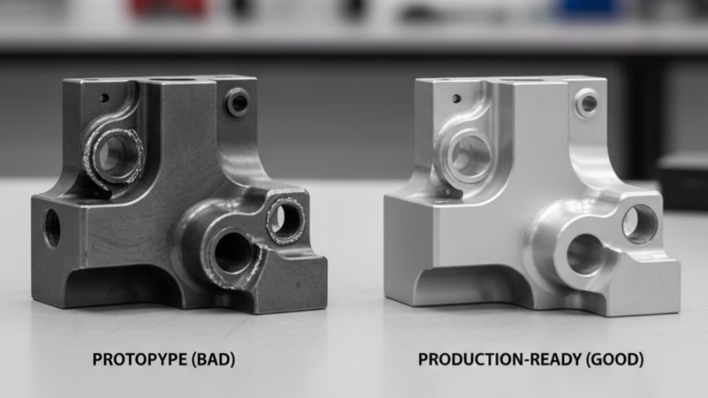
This isn’t just theory. Consider the real-world case of a fast-growing agricultural tech company we worked with. Their story is a masterclass in TCO thinking.
They came to us to produce a standard ABS plastic housing for a new soil sensor. The design required a separately sourced O-ring, manually installed with screws, to ensure it was waterproof. The request was for a competitive quote on 10,000 units. It was a perfectly viable, conventional design.
But our technical team saw a hidden risk. Here’s how the TCO Mandate reshaped their project and saved them over $120,000.
Lens 1: Design for Manufacturing (DFM) – The Cost of Creation
This is the most familiar lens. It asks: How efficiently and easily can this part be physically made? It scrutinizes factors like material choice, geometry, and tooling.
In our client’s case, the DFM analysis was straightforward for their initial design. However, our value-added insight was to challenge the entire premise. We proposed a switch from ABS to a more weather-resistant ASA material and, crucially, to use overmolding to integrate the seal directly into the housing.
This DFM change came with a trade-off: a 25% higher mold cost and a 15% higher part price. If we stopped thinking here, the idea would be rejected. But the other two lenses reveal the true story.
Lens 2: Design for Assembly (DFA) – The Cost of Integration
This lens asks: How easily and quickly can this part be integrated into the final product? It focuses on reducing assembly time and eliminating potential human error.
The overmolding solution was a massive win for DFA.
- Eliminated Assembly Costs: The manual process of installing 10,000 O-rings was completely removed from their assembly line.
- Eliminated Procurement Costs: They no longer needed to source, purchase, and manage inventory for 10,000 separate O-rings.
Lens 3: Design for Validation (DFV) – The Cost of Confidence
This final lens asks: How easily and reliably can we verify that the part and the final assembly meet quality standards? It targets failure rates, inspection time, and long-term reliability.
This is where the “more expensive” part created exponential value. The integrated, overmolded seal was far more reliable than a manually installed one. The result? A staggering 80% reduction in field failure rates compared to their previous product.
The cost of a single field failure—sending a technician, replacing a unit, and reputational damage—dwarfed the initial part price difference. By looking through all three lenses of the TCO Mandate, the client made a strategic decision.
The initial “higher price” was, in fact, an investment that yielded a return of over $120,000 in saved recall and repair costs in the first year alone. This is the power of shifting your focus from the price of a part to the total cost of its existence.
Your 5-Step Blueprint for Part Cost Optimization

Now, let’s translate the TCO framework into an actionable blueprint. Here are five concrete steps you can take directly within your CAD environment to optimize for total cost. Each step is a checkpoint, a question to ask yourself before you ever export that STEP file.
DfM Blueprint: At a Glance
| Step | Core Problem | Key Action |
|---|---|---|
| Step 1: Internal Corners | Sharp radii demand slow, expensive tooling. | Use radius ≥ 1/3 of cavity depth. |
| Step 2: Tolerance Zones | Over-tolerancing non-critical features. | Apply standard tolerances to non-functional surfaces. |
| Step 3: Holes & Threads | Non-standard specs require special tools. | Use standard drill sizes & minimum thread length. |
| Step 4: Aspect Ratios | Tall, thin walls cause vibration & inaccuracy. | Keep pocket depth ≤ 6x its width. |
| Step 5: Part Consolidation | Multiple parts increase assembly costs. | Integrate components where TCO is favorable. |
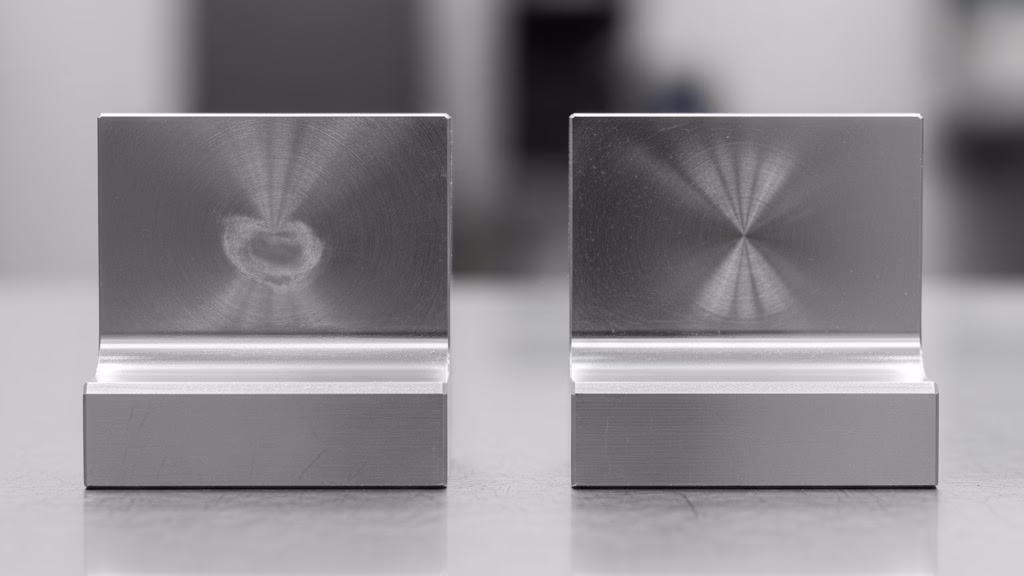
Step 1: Are Your Internal Corners Costing You a Fortune?
One of the most misunderstood cost drivers is the internal corner radius. A sharp or small internal corner forces a machine shop to use a smaller, more fragile, and more expensive cutting tool. This tiny feature can exponentially increase machining time due to slower speeds and multiple required passes.
As our own data shows, simply increasing the radius of internal corners from the commonly defaulted 1mm to a more generous 3mm or 6mm can reduce a part’s quoted price by an average of 18%.
Actionable Checklist:
- Default Rule: Make your inside corner radius at least 1/3 the depth of the cavity. For a 12mm deep pocket, specify a radius of 4mm or more.
- The Bigger, The Better: Unless it’s a critical mating surface, use the largest radius possible.
- Standardize: Use the same radius for all internal edges to eliminate the need for tool changes.
- Pro Tip: If you absolutely need a sharp internal corner for a mating part, consider designing a circular or undercut relief in the corner. This provides the needed clearance without the cost of slow, sharp-corner machining.
Step 2: Have You Declared “Tolerance Zones” on Your Drawing?
Over-tolerancing is the silent killer of project budgets.
As Application Engineer Eric Utley of Protolabs states, “A single unnecessary tolerance constraint on a drawing can force us to use a slower process, require more setups, and increase inspection time, easily doubling the cost of a feature for no functional gain.”
Actionable Checklist:
- Create Zones: Mentally (or physically on your 2D drawing) divide your part into “Critical Zones” and “Non-Critical Zones.”
- Critical Zones: These are the only areas that should receive tight tolerances—mating faces, bearing bores, press-fit holes, and other functional interfaces.
- Non-Critical Zones: For all other surfaces (housings, covers, non-functional faces), apply your shop’s standard tolerance (e.g., ISO 2768-m) or the loosest tolerance your design can functionally allow. This single action signals to your manufacturing partner where they can optimize for speed and efficiency.
Step 3: Are Your Holes and Threads Optimized or Over-Engineered?
Holes and threads seem simple, but non-standard specifications and poor practices in designing for tapping can add needless cost by requiring special tooling and processes.
Actionable Checklist:
- Hole Depth: Aim for a hole depth of no more than 4 times the diameter. Deeper holes can cause issues with chip evacuation and tool breakage.
- Standard Sizes: Whenever possible, use standard drill bit sizes. A 10mm hole is cheaper than a 10.15mm hole because it doesn’t require a custom reaming operation.
- Thread Length: Only specify the minimum thread length required for a secure connection. Tapping a hole all the way to the bottom is difficult and risky. Design for 2-3 extra threads beyond the required engagement length.
Step 4: Does Your Design Respect the Laws of Physics (Aspect Ratios)?
Tall, thin walls and deep, narrow pockets are classic red flags for machinists. They are prone to vibration, chatter, and deflection, which leads to poor surface finish, dimensional inaccuracy, and potential tool breakage.
Actionable Checklist:
- Wall Thickness: For machined plastic parts, a wall thickness of at least 1.5mm is a safe starting point. For metal parts, aim for at least 1mm. Anything thinner requires special handling.
- Rib-to-Wall Ratio: For injection molded parts, design ribs to be no more than 60% of the thickness of the wall they are attached to, preventing sink marks.
- Deep Pockets: The depth of any pocket or cavity should ideally be no more than 6 times its width.
Step 5: Can This Part Be Eliminated Entirely?
The most cost-effective part is the one you don’t have to make at all. Before finalizing your design, ask one final, critical question: Can this part’s function be integrated into another part?
Actionable Checklist:
-
- Review Assemblies: Look at any two parts that are fastened together. Can they be combined into a single, more complex part?
- Weigh the Trade-offs: A single, consolidated part might have a higher price than either of the two original parts, but it completely eliminates the hardware (screws, gaskets) and labor required to assemble them. Use the TCO Mandate to evaluate if the higher part price is justified by the savings in assembly and validation.
* Consult Your Partner: This is a perfect conversation to have with your manufacturing partner. Ask them, “If we combined these two components, what would the cost and performance trade-offs look like?”
How to Win in a World of Optimized Design
Congratulations. You now have a framework and a blueprint that put you ahead of 90% of your peers. By focusing on total cost, you’ve unlocked a powerful competitive advantage.
But what happens when everyone starts thinking this way? When AI-driven DfM tools make cost optimization a standard, automated step for all your competitors, where will your next advantage come from?
This is where you must evolve from a cost architect to a strategic player. The future of competitive product development will be fought on two new battlegrounds:
Gaining an Edge Through Strategic Choices:
While your competitors use automated tools that default to “safer,” cheaper 3-axis machining, you will gain an advantage by understanding when to strategically choose a “more expensive” process to achieve a lower total cost. When a part requires machining on more than two faces, don’t just accept the cheapest process.
Actively ask your manufacturing partner to quote a 5-axis, single-setup process. The reduction in setup time and increase in accuracy will often lead to a lower total cost—an advantage that standardized algorithms may miss.
Winning with Superior Agility:
As design optimization becomes commoditized, the real bottleneck will shift from design to delivery. Your advantage will no longer come from a slightly cheaper part, but from a partner who can respond faster, handle more complex logistics, and provide integrated services that your competitors can’t access.
The critical question will shift from “What is your price?” to “What is your lead time, and what other problems can you solve for me?”
Ready to Leverage 5-Axis Machining for a Competitive Edge?
Our 5-Axis CNC Machining service is designed to handle complex geometries in a single setup, reducing lead times and increasing part accuracy.
As Liam Casey, CEO of PCH International, wisely puts it, “Design for manufacturing is really about designing for the entire business… The best companies in the world understand that manufacturing isn’t a line item; it’s a competitive weapon.”
Choosing a manufacturing partner is no longer just a procurement decision. It’s a strategic choice. The right partner doesn’t just give you a price; they give you insights that protect your budget, improve your product, and secure your market position. By focusing on a supplier relationship that optimizes for total cost, you aren’t just buying a part—you’re buying a competitive edge.