Stop getting sky-high quotes or “No-Quote” replies for your CNC parts. This guide delivers the proven DFM rules to fix expensive deep pockets & narrow slots machining features before you ever ask for a quote. Learn how to optimize your CAD models to slash your manufacturing costs.
Deep pockets and narrow slots machining is expensive because it requires long, thin tools with a high Length-to-Diameter (L/D) ratio. These fragile tools suffer from severe tool deflection (bending), which forces machines to run extremely slowly to prevent vibration, inaccuracy, and breakage. This drastically increases machining time, CAM programming complexity, and overall cost.
Now, I’m going to show you the exact data, DFM golden rules, and supplier-vetting strategies you can use to solve this problem for good.
Why “Deep” and “Narrow” Are CNC Machining Nightmares

When a quote comes back high, your first feeling is frustration. But your second is probably confusion. “Why is it that expensive? It’s just a pocket.”
You’re not alone. The problem is that what looks simple in CAD software is often incredibly complex in the physical world. The high cost isn’t arbitrary; it’s dictated by physics. Let’s arm you with the data to show your team.
The Core “Devil’s Ratio”: L/D
The first and most important metric in machining is the L/D ratio. This is the ratio of the Length of the cutting tool’s reach to its Diameter.
In a perfect world, we use short, fat, incredibly rigid tools to remove material as fast as possible. But to machine your deep pocket or narrow slot, we’re forced to use a tool that is long and skinny.
This is where the costs explode. Here is a simple breakdown:
- L/D $\le$ 3:1 (The Standard): This is the baseline. We can use standard, rigid tools and aggressive feed rates. Your cost is 1x.
- L/D = 4:1 to 6:1 (The Tipping Point): The tool is less rigid and we must slow down. Our material removal rate (MRR) might drop by 50%, meaning machine time—and cost—starts to climb. Your cost is now 1.5x to 2.5x.
- L/D > 6:1 (The High-Cost Zone): The tool is now highly flexible. To prevent it from snapping, we must use incredibly slow speeds and shallow cuts. Machine time increases exponentially. Your cost can easily be 3x to 10x.
The Unbreakable Law of Physics: Tool Deflection
So, why do we have to slow down so much? The answer is tool deflection.
A long, skinny end mill acts just like a diving board—it bends. The amount it bends is governed by a nasty formula: Deflection $\propto$ L³/D⁴.
You don’t need to be a math wizard to see the problem. The relationship isn’t linear; it’s exponential.
- If you double the depth (L) of your pocket, the tool deflection increases by 8 times ($2^3$).
- If you halve the width (D) of your slot, the tool deflection increases by a catastrophic 16 times ($2^4$).
This single, tiny design change—”just make the slot a little narrower”—can have a 16x impact on the physical forces at play. This deflection is the root cause of all your problems:
- Vibration (Chatter): The tool bounces, leaving a terrible surface finish.
- Inaccuracy: The tool bends away from the wall, meaning the bottom of your pocket will be narrower than the top, failing to meet your tolerance.
- Tool Breakage: The tool flexes too much and snaps, stopping the job entirely.
The Two Hidden Cost-Killers You Don’t See
The high L/D ratio and tool deflection create two other massive costs that don’t show up on a simple time estimate.
- Chip Evacuation: In a deep pocket, the chips (the little metal shavings) have nowhere to go. They get packed at the bottom, and the coolant can’t get in to cool the tool. The only way to clear them is for the machine to stop cutting, pull the tool all the way out of the part (“pecking”), blast it with coolant, and then go all the way back down. This means for a deep pocket, your machine might spend 50% of its time cutting empty air, and you are paying for every second of it.
- CAM Programming Time: This is the big insight that most people miss. For a standard part, a CAM programmer might spend 30 minutes creating the toolpaths. For your L/D 8:1 part, that same programmer might spend 4 hours designing and simulating a highly complex “trochoidal” or “peel milling” path. They must test every possible way to sneak that fragile tool in and out without it exploding. You’re not just paying for “machine time”; you’re paying for high-level engineering services to even attempt the feature.
DFM Golden Rules: Eliminating 90% of Extra Costs in CAD
You’ve seen the “why.” Now, let’s focus on the “how.” The great news is that you, as the designer, have the power to eliminate the vast majority of these costs before the part ever gets to a machine.
It all happens in your CAD software. Here are the golden rules that will make you a hero to your manufacturing partners and your project manager.
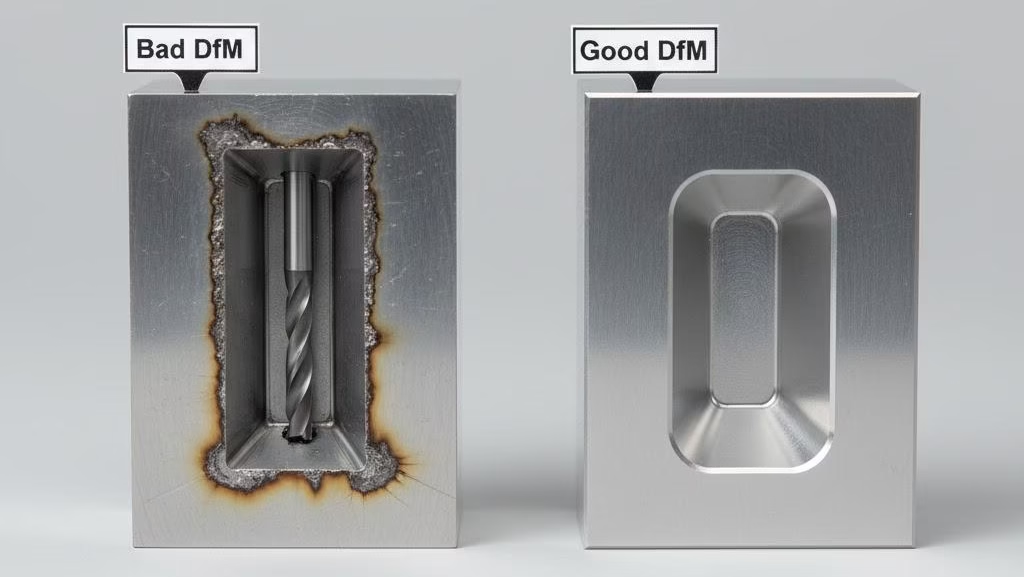
Rule 1: Optimize Your Internal Corner Radii
This is, without a doubt, the most common and costly DFM mistake. In CAD, it’s easy to create perfect, 90-degree internal corners (R=0). In milling, it’s physically impossible.
- The Cost Disaster: To get a “sharp” corner (e.g., R0.25mm) or a true R=0 corner, we can’t use a round milling tool. We must stop the CNC machine, take your part, and put it on a different machine called an EDM (Electrical Discharge Machine). This secondary process can increase the cost of that single feature by 300% to 500%.
- The Golden Rule: Make your internal corner radius at least 15% of the pocket depth. (Example: For a 10mm deep pocket, use at least an R1.5mm radius).
- Best Practice: Use the largest radius you can possibly get away with. A large radius (like 3mm or 6mm) allows us to use a larger, more rigid standard tool, which is exponentially faster.
Let’s look at a real-world cost comparison for the same pocket:
- Design A: Pocket with R0.5mm corners.
- Required Tool: $\phi$1mm (fragile, long-reach tool)
- Machining Time: ~120 Minutes
- Estimated Cost: $300
- Design B: Same pocket, but with R6mm corners.
- Required Tool: $\phi$12mm (standard, rigid tool)
- Machining Time: ~15 Minutes
- Estimated Cost: $40
That one change, which often doesn’t affect your part’s function, can save you $260.
Rule 2: Control Your L/D Ratio
Now that you understand the L/D ratio, you can control it.
- The Golden Rule: Whenever possible, design your pockets and slots to have a depth that is no more than 4 times the tool diameter (L/D $\le$ 4:1).
- The Design Trade-Off: Before finalizing that deep feature, ask yourself: Is this depth absolutely critical for the part’s function? Or was it just a default dimension? Can this slot be 6mm wide instead of 3mm? That simple change can cut the L/D ratio in half.
Rule 3: Relax Non-Critical Tolerances
Here’s another costly pitfall: applying a tight tolerance (like $\pm 0.02$mm) to a deep pocket wall or, even worse, the bottom of the pocket.
Thanks to tool deflection, holding that tolerance at the bottom of a deep cavity is a nightmare. It requires multiple, slow-speed “finishing passes” and on-machine inspection, all of which add time and cost.
- The Golden Rule: Never apply a tight tolerance to a feature unless it is absolutely critical for assembly or function. For most non-critical features, a standard tolerance (e.g., $\pm 0.1$mm) is 50% cheaper and more than sufficient.
To make this even easier, we’ve compiled these rules into a simple checklist you can use during your design reviews.
Get Your Design Reviewed by an Expert
The fastest way to reduce cost is to get an expert DfM review. Our engineers can analyze your file and show you exactly where the cost drivers are.
When the Design Can’t Change: Cost Analysis of Alternatives
Okay, so what happens when your project manager or the laws of physics simply won’t let you change the design? Sometimes, that 8:1 L/D ratio or that sharp internal corner is a functional requirement, not a style choice.
This is the moment you feel stuck between a rock (the design requirements) and a hard place (the budget).
Don’t panic. A good manufacturing partner won’t just say “no” or hand you a giant bill. They’ll help you navigate the alternatives. You have three paths forward, each with a very different cost structure.
Option 1: Stick with CNC Milling (The High-Cost Path)
If your L/D ratio is in that “grey area” (say, 6:1 to 10:1) and you’re only making a few prototypes, the simplest solution might be to just pay the high cost. This path accepts the reality of the physics we discussed.
You’ll be paying for that expert CAM programmer’s time and the extremely slow, careful machine cycles needed to get the job done without breaking tools. It’s not cheap, but for a one-off part, it might be faster than a total redesign.
Option 2: Switch to EDM (Electrical Discharge Machining)
This is your “Plan B” for features that are truly impossible for a milling cutter.
- When to use it: This is the only solution when your L/D ratio is extreme (like > 10:1) or when you must have sharp, R=0 internal corners.
- How it works: EDM uses a precisely shaped electrode and an electrical spark to “burn” away the metal, creating the exact shape you need.
- The Cost: The cost shifts. You’re no longer paying for long milling times or fragile tools. Instead, you’re paying for a new “NRE” (Non-Recurring Engineering) cost: the fabrication of the custom electrode. Then, you’re paying for the EDM process time, which is very slow but highly accurate.
Option 3: Redesign as a “Multi-Part Assembly”
This is a classic DFM (Design for Manufacturability) trick you’ve probably read about. “Why make one complex part when you can make two simple ones and bolt them together?”
But I have to give you a serious warning on this one, based on our own experience. This is not always cheaper.
We had a client who, trying to be helpful, took this advice and split a complex part into two flat plates to be assembled with screws. He thought he was saving us time. But his new “optimized” design ended up being 20% more expensive.
Why? He forgot to calculate the total cost.
His new design required:
- Two separate CNC machine setups (instead of one).
- Two separate parts to be fixtured and machined.
- Additional drilling and tapping operations (for the screw threads).
- The cost of the screws and washers.
- The manual labor time to assemble the two parts.
- The new risk of “tolerance stack-up” (the combined error of two parts fitting together).
In reality, for L/D ratios under 8:1, it’s often cheaper to just let a 5-axis CNC machine handle the complex pocket in one setup. Only consider the assembly option when the deep pocket is so extreme that the cost of Option 1 or 2 is truly astronomical.
| Cost Driver | High-Cost Design (The “Trap”) | Low-Cost Optimization (The “Fix”) |
|---|---|---|
| L/D Ratio | L/D Ratio > 6:1 (e.g., 2mm wide, 15mm deep) | Keep L/D Ratio < 4:1 (e.g., 4mm wide, 15mm deep) |
| Corner Radii | R=0 or R0.25mm (Requires EDM) | Use largest possible radius (e.g., R3mm or R6mm) |
| Tolerances | Tight tolerance (±0.02mm) on deep walls/floors | Relax to standard tolerance (±0.1mm) |
| Alternative | Keep as single part (often cheaper) | Split into multi-part assembly |
How to Use Your RFQ to Filter Suppliers
You now have the technical knowledge to fix your design. But here’s a final, crucial insight: you can use your RFQ (Request for Quote) as a powerful tool to find a true manufacturing partner.
Your goal isn’t just to find the cheapest quote. Your goal is to find the supplier who has the expertise to make your part successfully and efficiently. Here’s how you “interview” them without even picking up the phone.
Strategy 1: Demand the “A/B Quote”
This is the single most powerful strategy you can use. When you have a part with a costly feature (like a deep pocket), never accept a single quote.
Instead, you should proactively ask your supplier for two prices:
- Quote A (As-Is): “Here is the cost to make the part exactly as you designed it.” (This will be the $500 ‘shock’ quote).
- Quote B (DFM-Optimized): “And here is the cost if you make this one change we suggest (e.g., changing the R-corner to R3mm). We believe this will achieve the same function.” (This will be the $90 ‘solution’ quote).
This “A/B Quote” changes everything for you. It’s no longer just a price. It becomes a decision-making weapon. You can now walk into your project manager’s office and say: “We can have the design exactly as-is for $500. Or, we can make this small, non-critical change and get it for $90. Which do you want to do?”
You’re no longer the bottleneck. You’re the problem-solver who presents clear, data-driven options.
Strategy 2: Use the “Deep Pocket Trap” to Spot Red Flags
That difficult-to-machine deep pocket in your design? It’s not a problem; it’s a filter.
Think about it. When you send that RFQ out:
- 90% of suppliers (The “Quote-and-Pray” Shops): Will just send you a price. They either didn’t look at the file closely enough to see the difficult feature (a huge red flag) or they did see it and are just gambling that they can make it (or that you won’t check the quality).
- 10% of suppliers (The “Technical Partners”): Will come back to you before they quote. They will send an email saying, “Hey, we noticed this 8:1 L/D slot. Is this tolerance critical? We have a suggestion that could save you 40% on this part if you’re open to it.”
This is the supplier you want.
A partner who asks smart questions before production is one who will save you from disasters during production.
So, here’s your new rule: Never trust a supplier who doesn’t ask questions about your most difficult features. Use their silence as a red flag to instantly filter them out, no matter how low their price is.
Don’t Be a “Drafter,” Be a “Cost Translator”
Your value as an engineer isn’t just in your ability to draw a part. It’s in your ability to translate that design into a real-world, functional, and affordable component.
We’ve seen projects stall for weeks because an engineer (under pressure from an industrial designer) just “followed orders” and sent a design with a 1.5mm wide, 20mm deep slot to quote. They knew it would be expensive, but they didn’t know how to fight back.
Your greatest power is to be the “Cost Translator.” It’s the ability to look at that 1.5mm slot and tell your team, “I can translate that for you: it means $500 and a 4-week lead time.” And then, to follow up with, “But if we can change it to a 6mm R-corner, it translates to $50 and a 1-week lead time.”
You don’t have to bear this pressure alone. You shouldn’t have to guess.
A true manufacturing partner will do this work with you, at the quoting stage. They won’t just send you a high price; they’ll send you an analysis. They’ll show you why the cost is high and how to fix it. They won’t come to you mid-production telling you it can’t be done or that they need more money.
So, are you struggling with high quotes on your parts with deep pockets & narrow slots machining? Stop guessing and start collaborating.
Upload your CAD file today for a free, no-obligation DFM analysis report. We won’t just send you a price. We’ll send you a solution, showing you exactly how you can optimize your design to reduce costs by 50% or more.
References & Notes
[1] Tool Deflection Formula: The formula Deflection $\propto$ L³/D⁴ is a standard engineering principle derived from Euler-Bernoulli beam theory. It describes how a cantilever beam (like an end mill) deflects under a load. The key takeaway is the exponential relationship between length (L) and diameter (D), which is the primary physical constraint in deep pocket machining.
[2] CAM Programming: “CAM” stands for Computer-Aided Manufacturing. This software translates a 3D CAD model into G-code instructions that a CNC machine can understand. Advanced paths like “trochoidal milling” are specific strategies to manage high chip loads and tool engagement in difficult-to-machine features, like deep pockets, to prevent tool breakage.
[3] Tolerance Stack-Up: This is a critical DfM concept, especially for assemblies. It refers to the cumulative effect of individual part tolerances on the final assembly. A design with two parts, each with a ±0.1mm tolerance, could have a combined gap variation of ±0.2mm, which may impact its function. This risk is why “Design for Assembly” (DFA) must be carefully balanced against the cost of machining a single complex part.