Stop getting wildly different CNC quotes and parts that fail inspection. The problem isn’t your 3D model; it’s the critical information missing from your 2D engineering drawing. This guide shows you exactly what to add to get accurate quotes and perfect parts, every single time.
To get accurate CNC quotes, your 2D engineering drawing must include critical information not found in the 3D model. This includes:
1. Full material grade and temper (e.g., “Al 6061-T6”);
2. All post-processing and finish callouts (e.g., “Anodize Type II”);
3. A title block with general tolerances;
4. Specific dimensional and geometric tolerances (GD&T) on critical features;
5. General notes for threads, deburring, and inspection requirements.
You’ve seen the list, but how you apply this information is what separates a $1,500 “risk” quote from a $150 “partner” quote. We’ll break down the exact strategies, including real-world case studies of costly failures, to make your drawings “bulletproof.”
The Real-World Cost of a Vague 2D Drawing

These quoting and part failures aren’t theoretical. They are expensive, time-wasting realities that we see every week. The pain points are “quoting disasters,” “functional failures,” and “over-engineering penalties.”
The “$60 vs. $400” Quoting Disaster
Here is a story we’ve seen play out dozens of times. A startup engineer sends us an RFQ for 10 parts. The 2D drawing is simple, but for the material, it just says: “Material: Aluminum.”
Our estimator immediately hits pause and sends an email: “Which alloy and temper do you need? 6061-T6? 7075-T6? 5052?”
The engineer’s entire project is now stalled for two days waiting for this clarification. In the meantime, they get two other quotes:
- Supplier A (The Gambler): Assumes the cheapest option, 6061, and quotes $60/part.
- Supplier B (The Risk-Averse): Assumes the part might be for an aerospace application and quotes the most expensive option, 7075, at $400/part.
The engineer is now stuck, unable to explain to their manager why the quotes are 6-7x apart. Your drawing’s ambiguity created this chaos.
The lesson: Never use generic material names. “Aluminum,” “Steel,” or “Plastic” are invalid. A 2D drawing must specify the full grade and state, such as “Aluminum 6061-T6” or “SS 304, Annealed.” This is the #1 cause of quoting delays.
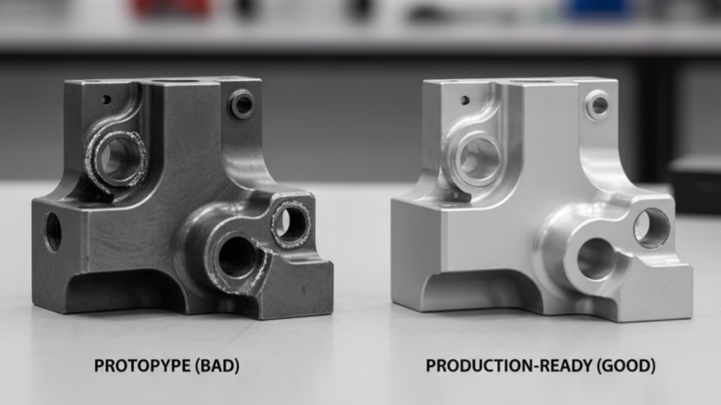
The “Functional Failure” from a Missing Detail
This case is even more painful. A senior engineer sent us a complex hydraulic manifold. The 2D drawing was beautiful, with perfect GD&T and tight tolerances. But he missed one callout: the surface finish on a critical inner bore designed for a piston seal.
We machined the part perfectly to his drawing. Every dimension was within tolerance. But we applied our standard machine finish (Ra 3.2 µm / 125 µin) to that un-specified bore.
The result? The parts were assembled, and the O-ring seals failed immediately, causing a catastrophic leak. The Ra 3.2 µm surface was far too rough for a dynamic seal. The entire project, involving expensive equipment, was shut down.
The lesson: Suppliers cannot read your mind. The engineer assumed we would know a seal requires a smoother finish (like Ra 0.8 µm). But the machinist’s golden rule is: “If it’s not on the print, it doesn’t exist.”
The “Crying Wolf” Engineer and the 3x Penalty
Finally, there’s the engineer who over-specifies. We received a drawing for a simple L-bracket. But the engineer had marked *every single dimension*—including non-functional outer edges and chamfers—with a tight ± 0.02mm tolerance.
Our quote was 3x higher than the engineer expected.
Why? Because to guarantee that every feature met this tight tolerance, we couldn’t use our standard 3-axis mill. We had to:
- Use our most precise 5-axis machine.
- Run it at a much slower feed rate.
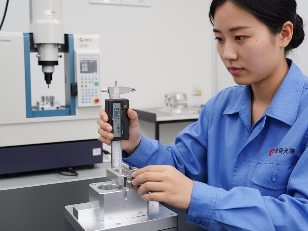
- Have a QC inspector check 100% of the dimensions in our CMM lab.
When the customer called, shocked by the price, we asked, “Do you really need this chamfer to be ±0.02mm?” The answer was, “Oh, no. Only the two assembly holes are critical.”
Don’t be the “crying wolf” engineer. When you mark everything as critical, nothing is. You are simply forcing suppliers to quote you a massive “risk penalty.”
Struggling with DfM and Costing?
These case studies are real. Before you quote, let our engineers provide a free Design for Manufacturability (DfM) review to catch costly errors hidden in your drawings.
The Three-Tier Information System for a “Contract-Level” Drawing
To prevent these failures, you need to think of your 2D drawing as a layered system. Each layer speaks to a different person in the manufacturing chain: the Estimator, the Machinist, and the Quality Inspector.
Your 3D model only speaks to the machine. Your 2D drawing must speak to the humans.
Tier 1: The Estimator’s “5-Second Check”
An estimator is busy. They receive dozens of RFQs a day. Your drawing must provide the most critical cost-driving information “above the fold,” just like a newspaper.
If they have to hunt for it, your quote goes to the bottom of the pile or gets a “risk markup.”
This information should be impossible to miss, placed clearly in the title block or a general notes section.
- 1. Full Material Grade & Temper: “Al 6061-T6” not “Aluminum.” “SS 304, Annealed” not “Stainless.” This is the #1 cost driver.
- 2. All Finishes & Post-Processing: “Anodize Type II, Black,” “Passivate per ASTM A967,” “Heat Treat to 45 HRC.” These secondary processes are often more expensive than the machining itself.
- 3. Your General Tolerances (The “Golden Rule”): This is the most important, yet most overlooked, part of the title block. A note like “UNLESS OTHERWISE SPECIFIED, TOLERANCES ARE: .XX = ± 0.1mm” tells the estimator that you are a professional. It signals that you won’t be the “crying wolf” engineer and that they can give you a fair price based on their standard process.
- 4. Quantity (Qty): Obvious, but essential for setup calculations.
Tier 2: The Machinist’s “How-To” Guide
Once the part is on the machine, the machinist takes over. They are not looking at the title block; they are looking at the part views. This is where you communicate *function*.
- 1. Specific Dimensional Tolerances: Use your “golden rule” from Tier 1 for 90% of your dimensions. Only apply tight, specific tolerances (e.g., ± 0.02mm) to the critical 10%—the features that actually mate, fit, or slide.
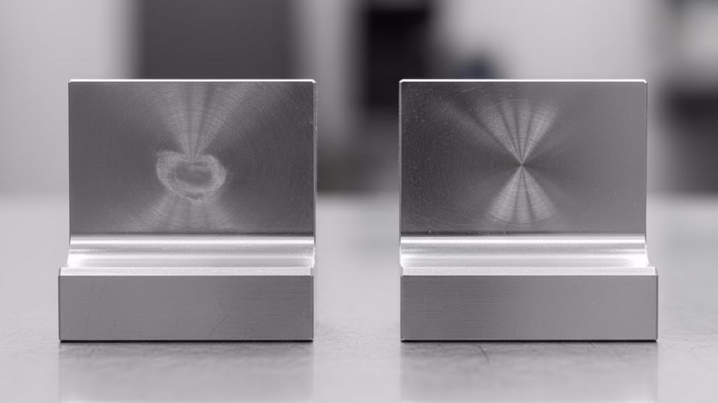
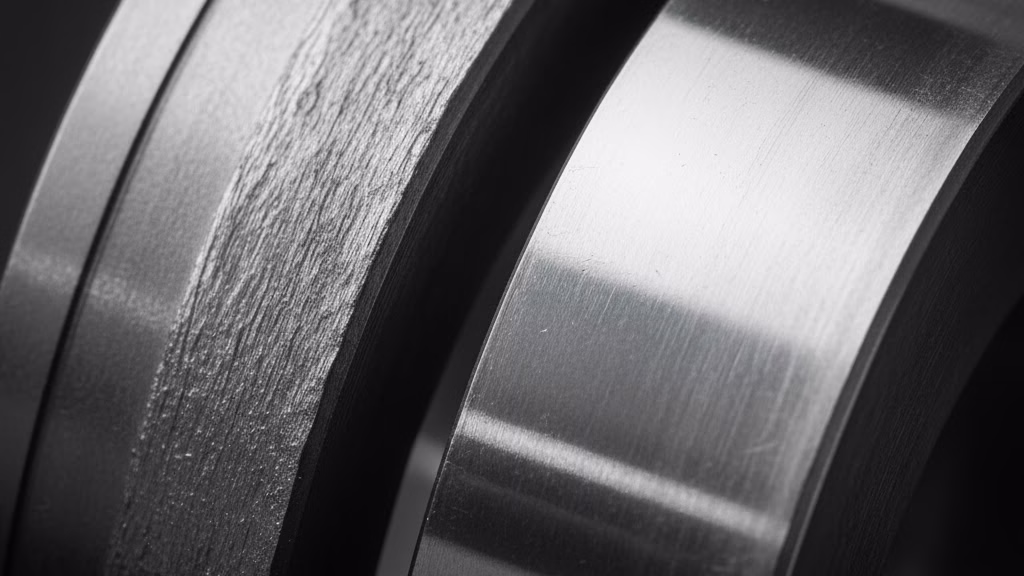
- 2. Surface Finish Callouts (Ra): That failed hydraulic seal taught us this. Your 3D model can’t show “smoothness.” You must call out the required surface roughness (e.g., Ra 0.8 µm) on any functional surface, like a seal face or bearing bore.
- 3. Full Thread Specifications: Don’t just show a hole. Define the thread: “M6 x 1.0 – 6H,” including the class of fit and depth.
- 4. Geometric Dimensioning & Tolerancing (GD&T): This is the ultimate language of intent. Use GD&T not to control a single feature, but to control the relationship between features, such as the position of a bolt pattern or the flatness of a sealing face.
Tier 3: The QC Inspector’s “Contract” (Your CYA)
This tier is what turns your drawing from a “sketch” into a “contract.”
As an expert from ASME (American Society of Mechanical Engineers) noted, the 2D drawing (or its data) “is the ‘contract’… It is the controlling document.”
This is your protection. These are the general notes that save you from “functional failures.”
- “REMOVE ALL BURRS AND SHARP EDGES.” The most common, and most critical, note.
- “MATERIAL CERTIFICATE REQUIRED WITH SHIPMENT.” This ensures traceability.
- “100% INSPECTION REPORT REQUIRED FOR ALL DIMS MARKED (C).” This is how you define which of the Tier 2 dimensions are truly critical to quality (CTQ).
| Information Tier | Primary Goal | Key Examples |
|---|---|---|
| Tier 1: Estimator | Accurate & Fast Quoting | Full Material Grade, Finish, General Tolerances, Qty |
| Tier 2: Machinist | Part Function & Manufacturability | Specific Tolerances, GD&T, Surface Finish (Ra), Threads |
| Tier 3: QC / Legal | Define Quality & Protect (CYA) | Deburring notes, Certifications, Inspection Reports |
Advanced Insights: Using Your 2D Drawing to Select Suppliers
Your completed 2D drawing is more than just a specification; it’s a powerful *supplier filtering tool*. The response you get to your drawing reveals everything about a supplier’s capability and professionalism.
The “Instant Quote” Trap
You’ve seen the automated quoting platforms like Xometry and Protolabs. You upload a 3D model and get a $100 “instant quote” in 30 seconds. It seems revolutionary.
But then, you attach your detailed 2D drawing (as a PDF) and submit the order. The next morning, you get an email: “After a manual review of your 2D drawing, your new quote is $550.”
This isn’t a bait-and-switch; it’s the system working as designed. The $100 was the “geometry price” calculated by the 3D model.
The $450 difference was the real cost of your “intent”—the tight tolerances, the Ra 0.8 surface finish, the heat treatment, and the GD&T callouts that the automated system could not read. That $450 is the price of the critical information we’ve been discussing.
Your 2D Drawing as a “Test”
This experience shows you how to choose your partner. Your drawing is a “test” that separates high-speed “digital platforms” from high-expertise “specialist shops.”
- Digital Platforms (Xometry, Protolabs, etc.): These platforms are built for standardization and speed. They are incredibly efficient for parts where the 3D model is the entire story—think simple brackets, housings, or parts with general tolerances. As Protolabs noted when expanding its services, it began “accepting 2D technical drawings… for your higher requirement projects,” which directly signals that 3D models alone are insufficient for complex, high-requirement parts.
- Specialist Job Shops (The Experts): These are the traditional, high-skill shops. They thrive on detailed 2D drawings. When they see your professional, clear, contract-level drawing, they don’t see a “problem”; they see a “high-quality customer.” Your drawing signals that you are an engineer who understands manufacturing, and it allows them to quote competitively based on their true expertise.
So, if your part is simple, a digital platform is a fast, efficient choice. But if your part is complex—if it has critical fits, tight GD&T, or specific functional requirements—your 2D drawing is your best tool for finding a true manufacturing partner.
From Chore to Strategic Weapon: Your Next Step
It’s time to stop thinking of your 2D engineering drawing as a chore. It’s not just the last, annoying step after you’ve finished the “real” work on the 3D model.
As we’ve seen, your 2D drawing is your single most powerful strategic weapon for managing cost, quality, and supplier relationships. It is the only document that translates your “intent” into a “contract.” It’s your primary tool for reducing costs at the design stage—long before any material is cut.
A professional drawing builds trust, eliminates ambiguity, and filters out unqualified suppliers. It’s the difference between a $150 part that fails and a $200 part that’s perfect—and it helps you avoid the $1,500 quote altogether.
Stop guessing. Let our engineers help you right now. Send us your current RFQ package (your 3D model and 2D drawing). We will provide you with a 100% free, no-obligation Design for Manufacturability (DfM) review. We’ll personally analyze your drawing and show you exactly where any hidden “cost traps” are.
Let us show you how to get your parts right, on time, for the right price. The critical information on your 2D engineering drawing is the key.
References & Notes
[1] On the Role of 2D Drawings (ASME): The quote “is the ‘contract’… It is the controlling document” is derived from guidance by the American Society of Mechanical Engineers (ASME), which establishes the Y14.5 standard for dimensioning and tolerancing, legally defining intent.
[2] CMM (Coordinate-Measuring Machine): A CMM is a device used in the quality control and inspection lab to measure the precise geometry of an object. Its use is required for verifying very tight tolerances that cannot be measured with standard calipers.
[3] Passivation Standard (ASTM A967): This is the industry-standard specification governing the chemical passivation process for stainless steel parts, which removes free iron from the surface to prevent rust.