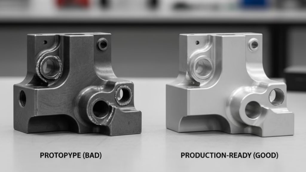
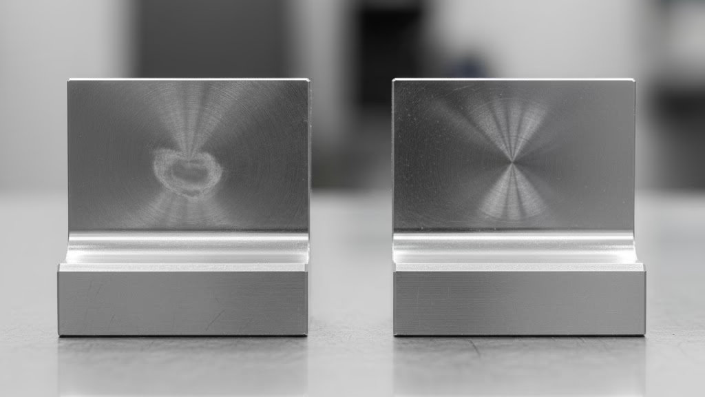
Getting high quotes on your machined parts? The culprit is almost always over-tolerancing. This data-driven guide shows you exactly why tighter tolerances increase CNC machining expense and provides actionable DFM (Design for Manufacturability) tips to lower your costs without sacrificing function.
Tighter tolerances increase CNC machining expense because they require more advanced machinery (like 5-axis vs. 3-axis), significantly slower machining cycle times, and expensive secondary processes like precision grinding. They also mandate 100% CMM inspection and lead to higher scrap rates, all of which add exponential cost.
In the full post, we’ll break down the specific cost multipliers for each tolerance level. You’ll also get a 3-step DFM toolkit to avoid over-engineering and cut your next machining quote.
A Data-Driven Look: How Tolerances Exponentially Increase Cost

The first thing to understand is that the relationship between tolerance and cost is not linear—it is exponential.
A 50% tighter tolerance does not equal a 50% increase in cost. As you shave off microns, the price climbs dramatically. Why? Because you are pushing against the physical limits of the machine, the material, and even the environment.
Let’s look at the data. Based on industry analysis of thousands of quotes, a clear pattern emerges. If we set a “standard” tolerance (e.g., $\pm 0.1\text{mm}$) as our baseline 1x cost, the impact of tightening it looks something like this:
| Tolerance Range (Bilateral) | Typical Process | Relative Cost Factor |
|---|---|---|
| $\pm 0.1\text{mm}$ (or $\pm 0.004″$) | Standard 3-Axis CNC | 1x (Baseline) |
| $\pm 0.05\text{mm}$ (or $\pm 0.002″$) | Precision CNC | 1.5x – 2x |
| $\pm 0.01\text{mm}$ (or $\pm 0.0004″$) | Precision + Secondary Ops | 4x – 8x |
| $< \pm 0.005\text{mm}$ (or $< \pm 0.0002″$) | Grinding / Lapping | > 10x |
This chart should be a wake-up call. That one $\pm 0.01\text{mm}$ callout on your drawing is actively telling the manufacturer to charge you 4 to 8 times more for that feature.
Many of us learned about the Taguchi Quality Loss Function in school, often represented as $L = k(y-m)^2$. This formula perfectly explains why this happens.
It states that cost (or “loss,” $L$) isn’t just a pass/fail switch that happens when you go “out of spec.” The cost begins to grow exponentially (the squared term) the instant a dimension ($y$) deviates from its perfect target ($m$).
As an engineer, when you demand a tiny tolerance, you are forcing us, the manufacturer, to fight that squared term. We have to spend an exponential amount of money (the $k$ constant) on better machines, slower processes, and advanced inspection just to keep that deviation near zero.
This isn’t just a manufacturing opinion; it’s a core principle of good design. The ASME Y14.5 standard—the literal rulebook for GD&T—is built on the concept that you should “specify tolerances no tighter than necessary to ensure proper function.” By this definition, over-tolerancing is officially not a best practice.
Unpacking the Black Box: Where Does That Extra Cost Go?
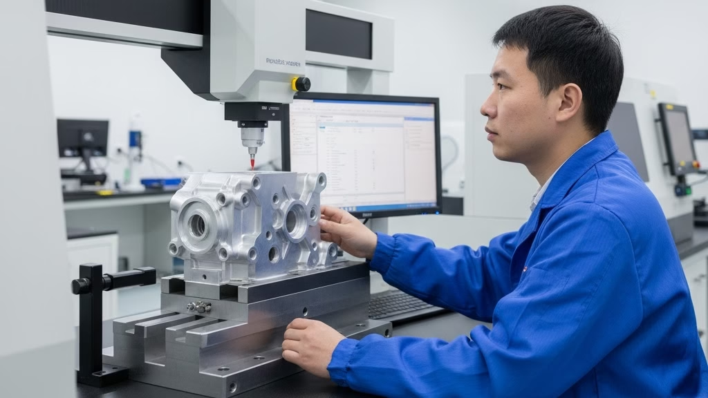
So, you see the cost multiplier, but why does it happen? That extra money isn’t just profit. It’s directly tied to the physical processes you force the manufacturer to adopt.
When we see a tight tolerance, we have to change everything about how we make your part.
Process, Machines, and Time
This is the most direct cost. Your tolerance callout dictates the machine, the speed, and the process itself.
- Standard Tolerance ($\pm 0.1\text{mm}$): We can run this part on a standard 3-axis CNC mill. We’ll use a fast feed rate and can often complete the feature in a single pass. This is fast and economical.
- Precision Tolerance ($\pm 0.02\text{mm}$): This tolerance triggers a “finishing pass.” We have to slow the machine down, take a much shallower cut, and possibly use a brand-new tool to avoid deflection. We may also need to stop and measure the part multiple times. This can easily increase the machining cycle time by 200%.
- Ultra-Precision Tolerance ($< \pm 0.01\text{mm}$): You are no longer buying a simple CNC milling service. To hold this tolerance, we are forced to move your part to a completely different, far more expensive process. We may have to CNC mill the part first, then send it to a climate-controlled room for precision grinding or EDM (Electrical Discharge Machining). The hourly rate for these machines can be 5 times that of a standard CNC.
The Unseen Cost of Quality Control (QC)
How do you prove a part is within tolerance? This is a huge, hidden cost.
- Standard Tolerance: We can use calipers or a micrometer. We’ll do a statistical sample, maybe checking 1 out of every 10 parts. This takes a few seconds.
- Precision Tolerance: Calipers are no longer accurate enough. You have just mandated the use of a CMM (Coordinate Measuring Machine). A CMM is a slow, extremely expensive piece of metrology equipment. We now have to stop production and 100% inspect every single part. Programming and running a CMM check can add 5 to 15 minutes of pure, non-value-added cost to every part you order.
The Price of Risk and Scrap
Finally, when you ask for perfection, you have to pay for the risk of failure.
- Standard Tolerance: Our process is stable. We have a wide margin for error, and our scrap rate is very low (e.g., < 2%).
- Precision Tolerance: The game changes. Now, a tiny vibration, a 1-degree change in room temperature causing thermal expansion, or microscopic tool wear can cause the part to be “out of spec.” Our scrap rate will unavoidably climb, perhaps to 5% or 10%.
As a manufacturer, we must price this risk into your quote. That 5-10% expected scrap cost is built directly into your unit price. When you relax a non-critical tolerance, you are directly helping us lower our risk, and in turn, we can give you a lower price.
Your DFM Toolkit: How to Immediately Lower Machining Costs
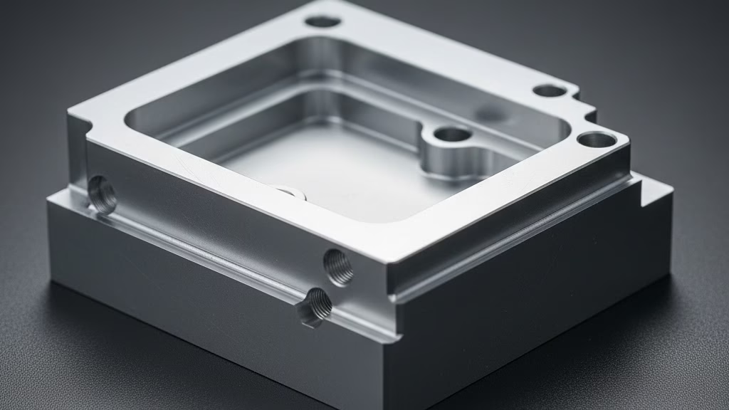
Knowing why tolerances are expensive is only half the battle. Now, let’s talk about what you can do about it.
These practical Design for Manufacturability (DFM) tips are the tools you need to solve the over-engineering problem and significantly reduce your costs.
Separate “Critical” from “Non-Critical”
This is the golden rule of cost-effective design. On any given part drawing, 90% of the features are likely “non-critical.” They simply need to exist; their exact size is not vital to the part’s function.
Your job as a designer is to identify the 10% that are critical. Ask yourself: does this feature directly impact assembly, fit, or function?
- A hole for a press-fit bearing? Critical.
- A surface that mates with another part? Critical.
- The outer profile of a plastic enclosure? Probably non-critical.
- A recessed pocket for a logo? Definitely non-critical.
Apply your tight tolerances only to the critical features. For everything else, relax.
Avoid Over-Engineering Your Design
Our DFM experts help you find the perfect balance between tolerance and cost. Get a free DFM review today to see how you can lower part costs without sacrificing function.
Use GD&T Smarter (It’s Often Cheaper)
There’s a common misconception that Geometric Dimensioning and Tolerancing (GD&T) is always expensive. This is incorrect. When used properly, GD&T can be significantly cheaper than using tight linear (±) tolerances.
Here’s a common example: Imagine you have four mounting holes that need to align with another part.
- The Expensive Way: You put a tight linear tolerance (e.g., $\pm 0.01\text{mm}$) on the X and Y coordinates for all four holes. This forces the machinist to chase perfection on eight different dimensions.
- The Cost-Effective Way: You use a True Position callout to control the relative location of the four holes to each other, and then you relax the linear tolerance for each individual hole.
This tells the machinist what truly matters (the hole pattern), allowing them to use a more standard, economical process to place the holes. You get the function you need, for a fraction of the cost.
Embrace General Tolerances (Like ISO 2768-m)
This is the easiest and most effective way to save money. Instead of letting your CAD software’s default (and often tight) title block tolerance control every feature, specify a general tolerance standard.
We had a startup client come to us with a beautiful aluminum housing. Their title block had a default tolerance of $\pm 0.05\text{mm}$ for everything. The quote was, unsurprisingly, very high.
Our engineer called them and asked, “Do you really need this logo pocket and these outer curves held to $\pm 0.05\text{mm}$?”
The designer was surprised: “Oh, heavens no. Only the PCB mounting holes are critical.”
We suggested they keep the tight tolerance on those few holes but add one note to the drawing: “UNLESS OTHERWISE SPECIFIED, ALL DIMENSIONS PER ISO 2768-m.”
That one sentence allowed us to use our standard, economical processes for 95% of the part. We re-quoted the job, and the new price was 40% lower. That is the power of communicating your intent.
Industry Traps: 3 Expensive Mistakes Engineers Overlook
Even with the perfect DFM toolkit, there are three hidden traps that we see engineers fall into all the time. These are the “unwritten” rules of manufacturing that can silently inflate your budget.
Trap 1: The Post-Processing Tolerance Stack-Up
You must design for the entire process, not just the machining. Heat treatment and surface finishes (like anodizing) are not just cosmetic; they physically change your part.
Case 1: The Heat Treatment Nightmare.
We had a 4140 steel part where the engineer specified a flatness of $0.02\text{mm}$ after heat treatment to HRC 58. The problem? 4140 steel will warp during hardening, often by more than $0.1\text{mm}$. To meet that spec, we had to add a completely new, expensive step: precision grinding the part after it was hardened. That one note on the drawing increased the part cost by 5x.
Case 2: The Anodizing Illusion.
A client designed a USB-C port with a $\pm 0.02\text{mm}$ tolerance after black anodizing. But Type II anodizing adds a layer of material. To hit that final dimension, we had to machine the raw part to an insanely tight $\pm 0.007\text{mm}$ to compensate for the anodize build-up. The engineer thought they were specifying a standard tolerance, but they had actually forced us into an ultra-precision process.
Trap 2: The “Gamble” of a Low Quote
This is a critical insight. You may get two quotes: one from us for $180, and one from a small shop for $100. The $100 quote is tempting, but it’s a trap.
That $100 quote is a “gamble.” The shop is betting they can hit your tolerances on their standard machine. They won’t use a CMM, and they are counting on you not checking every part. You will receive parts with terrible consistency, leading to assembly failures and line-down situations.
Our $180 quote is not a “processing fee”; it’s a “process guarantee.” That price includes the use of our high-precision machine, a climate-controlled environment, and 100% CMM inspection. You aren’t paying for machining; you are paying for the certainty that every single part you receive will be identical and in-spec.
Trap 3: The “Dumb Drawing” Paradox
Engineers often think a “clean” drawing with a simple, default title block tolerance (e.g., $\pm 0.05\text{mm}$ for everything) is professional.
In manufacturing, this is the most expensive drawing you can make.
We call it a “Dumb Drawing” because it gives us no context. We have to assume every single feature—every chamfer, every radius, every non-critical edge—is vital. To protect ourselves, we must use our most precise, slowest, and most expensive process for the entire part.
A “Smart Drawing” does the opposite. It uses ISO 2768-m for general features and only calls out the 3-4 critical tolerances. This “smart” drawing, by giving us context, allows us to use economical processes on 95% of the part, often saving you 30% with no functional change.
From Quote to Partner: A Smarter Way to Manufacture
The most cost-effective parts are not just “designed” and then “quoted.” They are the result of early collaboration between you, the designer, and us, the manufacturer.
You should not have to bear the cost of over-engineering or navigate the complexities of manufacturing processes alone. The goal is to get your part’s function at the best possible price.
Here is your call to action:
- Try this on your next design: On your next non-critical part, apply the ISO 2768-m general tolerance standard and see what happens to your quotes.
- Let us help you directly: Are you looking at a drawing right now and wondering if your tolerances are too tight?
Stop guessing. Upload your CAD file to our secure portal today. Our engineering team will provide you with a free, professional DFM (Design for Manufacturability) feedback report. We will pinpoint exactly which tolerances are driving up your price and suggest specific changes to reduce costs—all before you ever place an order.
Let’s work together to build better, more economical parts and stop the cycle of how tighter tolerances increase CNC machining expense.
Stop Guessing. Start Optimizing.
You’ve seen the data. Now let our experts apply it to your project. Upload your drawing for a free, no-obligation DFM review and discover exactly how much you can save.
References & Notes
[1] Taguchi Quality Loss Function: This refers to the engineering philosophy pioneered by Dr. Genichi Taguchi, which states that any deviation from a target nominal value results in a “loss” to society. This quadratic loss model ($L = k(y-m)^2$) is a foundational concept in Six Sigma and modern quality control, mathematically explaining why achieving “tighter” tolerances (minimizing deviation $y-m$) incurs exponentially higher manufacturing costs ($k$).
[2] ASME Y14.5: This is the standard for Geometric Dimensioning and Tolerancing (GD&T) published by the American Society of Mechanical Engineers. It provides the symbolic language and rules used on engineering drawings to define the allowable variation of features. The principle cited is fundamental to DFM, ensuring that tolerances are specified based on function, not default values.
[3] ISO 2768-m: This is an ISO standard for general tolerances for linear and angular dimensions without individual tolerance indications. The “-m” designates the “medium” (mittlere) class, which is a common, economical standard for features where function is not critically affected by dimensional variation.
