Stop getting your CAD files rejected by machine shops. This no-fluff guide gives you an actionable, field-tested checklist to fix the most common CAD file errors that lead to costly CNC machining rework. Use these steps to save your project time, budget, and frustration.
The five most common CAD file errors in CNC machining are: incorrect tolerance specification (like over-using default global tolerances); unmanufacturable geometry (such as zero-degree internal radii and overly thin walls); sending only a 3D model without a 2D drawing to define intent; corrupted or non-manifold geometry from bad file exports; and incorrect file units or scale (e.g., inches vs. mm).
Now that you know what the errors are, it’s time to learn the simple, step-by-step process to find and fix them before you send your file.
The True Cost of Rework: Far More Than You Imagine
You might be thinking, “It’s just a 30-minute file modification. What’s the big deal?”
The problem is, the time you spend modifying the CAD file is only the tiny, visible tip of the iceberg. The real costs of rework are hidden beneath the surface, and they are catastrophic for your project.
The “Schedule Collapse”
Here’s what actually happens when we send that “file error” email:
- Your project is immediately paused.
- The CNC machine slot we had reserved for your job? It’s instantly assigned to another customer who has a file ready.
- When you send the corrected file back 24 hours later, you don’t get your old spot. You go to the back of the line.
That “30-minute fix” just caused a two-week delay as you wait for the next available machine slot.
The “Trust Erosion”
Worse than the schedule hit is the invisible damage. When your files consistently cause delays, your project managers and procurement teams start to lose confidence.
They may not say it, but they start thinking, “This engineer’s files always have issues. Maybe we should budget extra time,” or, “Are these designs reliable?” This erodes your professional authority and makes every future project more difficult.
The Exponential Money Cost
Finally, let’s talk about the real-world cost. Tolerances are a primary driver of price. But the cost isn’t linear—it’s exponential.
A manufacturer-focused study on DFM (Design for Manufacturability) found that 70% to 80% of a product’s life-cycle costs are locked in during the design stage. Your tolerance decisions are a huge part of this.
For example:
- Machining a part to a standard tolerance of $\pm0.010”$ ($\pm0.25mm$) has a baseline cost.
- Tightening that same feature to $\pm0.005”$ ($\pm0.12mm$) can increase the cost 1.5x.
- Tightening it further to $\pm0.001”$ ($\pm0.025mm$) can easily multiply the cost by 3x to 5x.
Why? Because it requires slower machine speeds, more expensive tools, and advanced inspection (like a CMM). When your drawing demands unnecessary precision, you are designing high costs and a high risk of rework right into the part.
So, how do you prevent this disastrous chain reaction? It starts by identifying and eliminating the 5 biggest culprits.
The 5 Culprits of CNC Rework (And How to Fix Them)

This is the core of the problem. We’ve found that almost all rework can be traced back to these five common CAD file errors.
For each culprit, we’ll explain what it is, why it’s a critical problem for you (the engineer), and a simple checklist to eliminate it from your designs for good.
Culprit #1: The Tolerance Trap (“Default Values” & “Over-Engineering”)
This is, without a doubt, the most expensive mistake in CNC machining.
What It Is: The error happens in two ways:
- The “Default” Trap: You use your CAD software’s default title block, which has a “global tolerance” like $\pm0.05mm$ ($\pm0.002”$) that gets applied to every single dimension on the drawing.
- The “Just in Case” Trap: You aren’t 100% sure what tolerance a feature needs, so you specify a tight one “just to be safe.”
Why It’s a Problem: You are designing a part that is either absurdly expensive or literally impossible to make. As Greg Paulsen, Director of Application Engineering at Xometry, has pointed out, many file errors are “knowledge gaps.” Engineers don’t intend to make unmanufacturable parts; they are simply unaware of the specific constraints.
Real-World Experience: The “$800 Enclosure”
We recently had a startup engineer quote a 6061-aluminum enclosure, about 300mm long. Our system quoted it at nearly $800 per piece.
Why? His 2D drawing had a default global tolerance of $\pm0.05mm$. This meant the 300mm overall length, the 200mm width, and the 80mm height all had to be held to this extreme precision. This requires a climate-controlled room, a CMM for inspection, and painfully slow machining.
We didn’t just reject the file. We called him and asked one simple question: “Does this enclosure need to hold this tolerance, or is it just the default on your template?”
His answer: “Oh god, that’s just our default template. It’s a lid for a prototype, $\pm0.5mm$ is totally fine.”
We had him update the drawing to the industry-standard ISO 2768-m (medium) and only call out tight tolerances on the critical mounting holes.
The result? The price dropped from $800 to $220.
We didn’t just save him from a parts rework; we saved his entire project from a budget-killing “rework.”
Your Rework-Prevention Checklist:
- [DELETE] the global tolerance from your drawing’s title block.
- [USE] a standard baseline tolerance like ISO 2768-m (medium).
- [ASK] this one question for every feature: “What does this surface mate with?” If the answer is “nothing” or “air,” it does not need a tight tolerance. Save your budget for the features that truly matter.
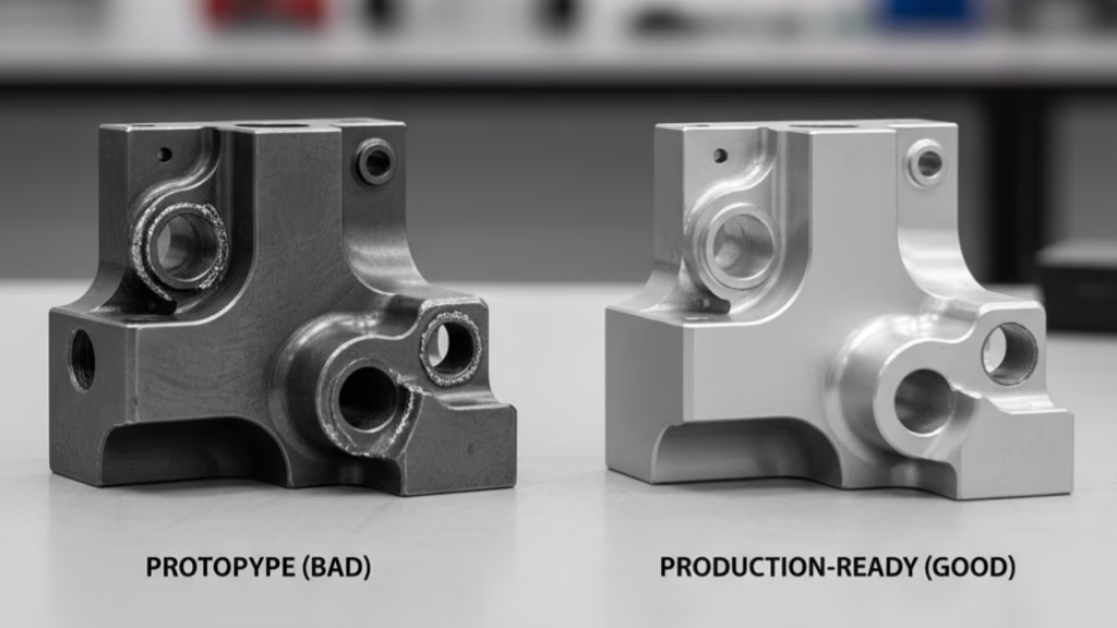
Culprit #2: Unmanufacturable Geometry (Zero Radii, Thin Walls)
As an engineer, you work in the digital world of CAD, where a perfect 90-degree internal corner is just a click away. In the physical world of CNC machining, this is a fantasy.
What It Is: This error involves designing features that are either physically impossible for a machine to create or are unstable during the machining process. The two most common are:
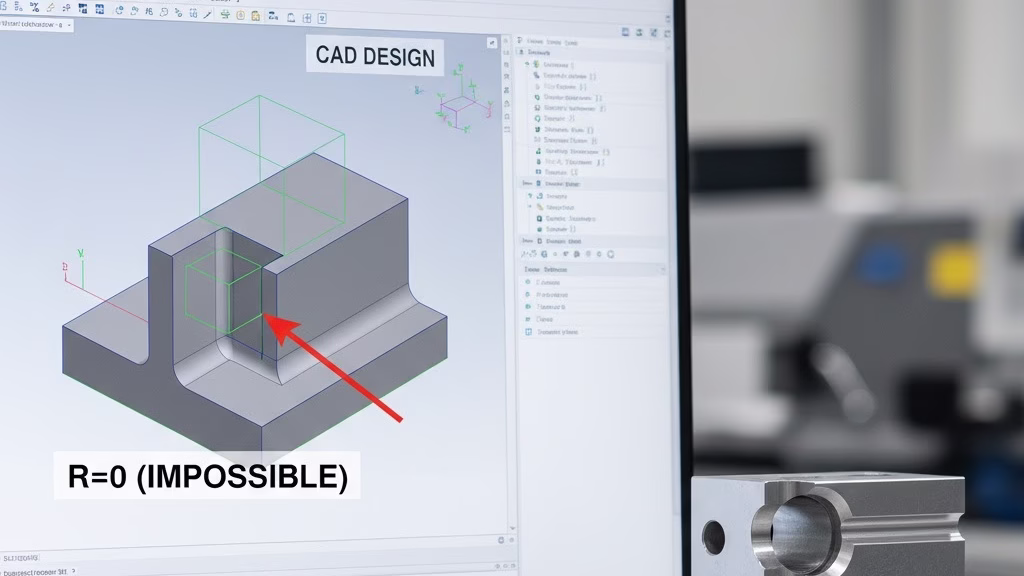
- Zero-Radius Internal Corners: Designing sharp, 90-degree internal corners (R=0).
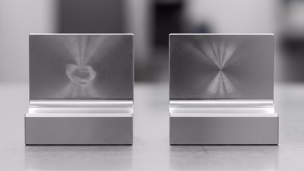
- Overly Thin Walls: Designing walls that are too thin relative to their height.
Why It’s a Problem:
- Zero Radii: A CNC end mill is a cylindrical cutting tool. It is physically impossible for a round tool to create a sharp internal square corner. This immediately leads to a “No-Quote” or a rework request.
- Thin Walls: When a tool machines a thin wall, the wall vibrates violently (called “chatter”). This vibration leads to a terrible surface finish, dimensional inaccuracy, and, in many cases, causes the wall to deform or break entirely. The part is scrapped, and you have to start over.
As Professor John Hart of MIT puts it, “A file that ignores the constraints of the machine… is not a design, it’s a fantasy. The rework comes from translating that fantasy into reality.”
Real-World Experience: “The Impossible Right Angle”
We had a client from a major engineering firm send us a STEP file for a part with a groove. This groove needed to mate with a square slider. The CAD model, of course, had perfect R=0 internal corners.
Our CAM software flagged it instantly.
We could have just rejected the file and said, “Unmanufacturable. Fix it.” This is what creates friction and frustrates engineers.
Instead, we sent him a simple screenshot showing our 3mm tool and the R=1.5mm radius it would unavoidably leave behind. We then proactively offered two “engineer-friendly” solutions:
- Solution A (Dog-Bone): Add a “dog-bone” or “Mickey Mouse ear” relief in each corner. This small cutout allows his square slider to fit perfectly, even though the groove’s corners are rounded.
- Solution B (Radius): Simply change his design to have an R=1.5mm (or larger) radius, which we could machine easily.
He replied in five minutes, “Wow, thanks for the clear explanation. Dog-bones added.” He sent the new file, and we started machining that day. We helped him avoid a costly, slow alternative like EDM (Electrical Discharge Machining) and, more importantly, we avoided a rework loop.
Your Rework-Prevention Checklist:
- [CHECK] all internal corners. As a rule of thumb, design internal radii to be at least 1mm (or 1/3 of the pocket depth). Bigger is always better and cheaper.
- [APPLY] “dog-bone” reliefs if you absolutely must have a square part fit into the corner.
- [OBEY] the wall ratio. For aluminum, a safe guideline for wall height-to-thickness is 30:1. If your wall is 30mm tall, it should be at least 1mm thick.
Culprit #3: The “Single Source of Truth” Lie (Sending Only a STEP File)
In modern CAD/CAM workflows, there’s a strong push for “MBD” (Model-Based Definition), where the 3D model (like a STEP file) is the “single source of truth.” In a perfect world, this is correct. In the real world of high-precision CNC machining, this is incredibly dangerous.
What It Is: You believe the 3D model is everything, so you send only a .STEP or .X_T file to your vendor, with no accompanying 2D engineering drawing.
Why It’s a Problem: This is one of the most overlooked common CAD file errors. The issue is this: The 3D model defines the geometry, but it fails to define the intent.
When our machinist opens your STEP file in their CAM software, they see a perfect piece of geometry. But they don’t know:
- Is this hole for a clearance screw (loose tolerance), or is it for a press-fit bearing (critical tolerance)?
- Does this surface need a specific finish (Ra)?
- What is the flatness requirement for this top face?
- Do these edges need to be deburred or chamfered?
How the disaster happens: The machinist has to “guess.” To be efficient and cost-effective, they will machine it to standard, economical practices. When the part is delivered, you discover the bearing won’t fit.
That is rework. But technically, it’s not the supplier’s fault. They manufactured your 3D model 100% perfectly. Your missing “intent” is what caused the rework.
Your Rework-Prevention Checklist:
- [PACKAGE] Your RFQ must be a “Tech Pack”: 1 STEP File (for CAM programming) + 1 PDF Drawing (to define “intent”).
- [ANNOTATE] You don’t need to dimension everything on the PDF. Just clearly call out the 4 critical things the STEP file cannot carry:
- Critical Tolerances (GD&T): Only on mating features.
- Surface Finish (Ra): Which faces, and how smooth?
- Material & Heat Treat: Be specific (e.g., AL 6061-T6).
- Thread Specs: (e.g., M6x1.0-6H).
This PDF is the “contract” between you and the machinist. It is your ultimate insurance policy against rework.
Culprit #4: Corrupted Geometry (Non-Manifold, Open Contours)
This error is sneaky. Your CAD model looks perfect on the screen, but “mathematically,” it’s broken.
What It Is: When you export a file from certain 3D modeling software (especially mesh-based programs like Rhino, Blender, or SketchUp), or during complex surfacing, the model can develop tiny surface breaks, overlapping faces, or unstitched gaps (open contours). The technical term for this is “Non-Manifold Geometry.”
Why It’s a Problem: Your CAD software might “tolerate” this error, but your vendor’s CAM (Computer-Aided Manufacturing) software absolutely will not. CAM software needs a “watertight,” mathematically perfect solid model to calculate its toolpaths.
When it encounters non-manifold geometry:
- The file may fail to import entirely.
- The software will miscalculate a toolpath, sending a tool plunging into an area it shouldn’t.
- Worst of all, the toolpath calculation fails at the last step, causing the part to be scrapped on the machine.
Your Rework-Prevention Checklist:
- [USE TOOLS] Don’t just trust your eyes. Use your CAD software’s built-in diagnostic tools.
- In SolidWorks, use ‘Tools’ > ‘Evaluate’ > ‘Check’.
- In Fusion 360, use ‘Section Analysis’ to inspect for internal abnormalities.
- [FORMAT] Stop using .STL or .IGES files. .STL is a mesh for 3D printing, not CNC. .IGES is an old standard that frequently causes surface translation errors.
- [INSIST ON] STEP AP214 or Parasolid (.x_t). These are modern, robust, solid-body-native formats designed to minimize data corruption.
Culprit #5: Units & Scale (The “Ant-Sized” Part)
You might laugh, but this is absolutely one of the most common CAD file errors—and the most embarrassing.
What It Is: You are based in the US and are used to designing in an Imperial (Inches) software environment. But the CNC machining industry (and most of the world) defaults to Metric (Millimeters). When you export your file, the software incorrectly saves your 25.4-inch part as 25.4 millimeters.
Why It’s a Problem: This is a pure, 100% waste of time. Your vendor’s engineer opens your file, ready to quote your 2-foot-wide enclosure. Instead, they see a model that is the size of a fingernail (approx. 25.4mm).
They cannot quote it. They can only send you an email: “Your file units appear to be incorrect. Please confirm and resend.”
You modify the setting in embarrassment, re-export, and resend. You have once again entered the “rework loop” and delayed your project by a day over something that could have been avoided in 10 seconds.
Your Rework-Prevention Checklist:
- [THE GOLDEN RULE] Before you hit ‘send’ on that RFQ email, ALWAYS, ALWAYS re-open the exact STEP file you just exported.
- [VERIFY] Use the measure tool and check one known master dimension (like overall length or width).
- [CONFIRM] That your 300mm part reads as 300mm, not 11.81 (inches). This 10-second self-check will save you 24+ hours of delays.
Quick-Fix Table: The 5 Common CAD Errors and Their Solutions
| CAD Error Culprit | Why It’s a Problem (The “Pain”) | The 1-Step Solution |
|---|---|---|
| 1. The Tolerance Trap | Sky-high costs or 100% rework risk. | Use ISO 2768-m; only tolerance critical features. |
| 2. Unmanufacturable Geometry | No-Quote, part deformation, or scrapped parts. | Add radii (>=1mm) to internal corners or use “dog-bones”. |
| 3. Missing 2D Drawing | Supplier has to “guess” your intent (tolerances, finish). | Always send a PDF drawing with your STEP file. |
| 4. Corrupted Geometry | CAM software cannot read the file or creates bad toolpaths. | Use ‘Check’ tool in CAD; export as STEP AP214. |
| 5. Incorrect Units/Scale | A 100% waste of time; file is rejected immediately. | Re-open your own STEP file and measure it before sending. |
The Mindset Shift: From “Engineer” to “Manufacturing Partner”

Congratulations. You now have the technical fixes for the 5 most critical errors. But that’s not enough.
Engineers who truly “say goodbye to rework” don’t just have the right technical skills; they have a “manufacturing mindset.” This means thinking beyond the CAD file and fundamentally changing how you interact with the manufacturing process.
Insight 1: Beware the “Instant Quote” Trap
The industry trend is “AI-powered instant quoting.” You upload your 3D model and get a price immediately. It feels great, right?
This is a trap. The primary goal of these quoting engines is to “get the sale,” not to “prevent errors.” They may not detect that thin wall that will vibrate, or that deep pocket requiring special tooling. They give you a tempting low price.
The disaster happens after you place the order. The file hits a human review, and the error is finally caught. Now the supplier gives you two options: 1) Cancel the order (rework, schedule collapse), or 2) Accept a 3x price increase.
Your takeaway: Never equate an “instant quote” with a “manufacturability analysis.” A good partner will proactively point out problems with their quote.
Insight 2: Treat Your Supplier as a “Consultant,” Not an “Executor”
Don’t be afraid to talk to your supplier. In your RFQ email, add this one simple question:
“What modifications would you recommend to my current design to reduce cost and rework risk?”
This question immediately filters out commodity shops. A shop that only executes will say, “Looks fine.” A true “consultant” partner will reply, “We noticed your internal radius is R=2.8mm. If you change that to R=3.0mm, we can use a standard tool and lower your machining costs by 15%.”
Insight 3: Design Using “Standard Tool Sizes”
This is an advanced-level tip. When designing a pocket, do you prefer R=2.8mm or R=3.0mm? R=5mm or R=4.9mm?
Your CAD software doesn’t care, but the CNC machine definitely does. A machinist’s standard end mills are typically D=2, 4, 6, 8, 10mm (giving radii of R=1, 2, 3, 4, 5mm). If you design an R=2.8mm radius, they must either use expensive “non-standard” tooling or use a much smaller tool (like D=4mm) and take 5x as long to “mill out” that specific radius.
Your takeaway: Whenever possible, design your fillets and radii using standard integer radius sizes (R=1, 2, 3, 4, 5mm, etc.). This dramatically lowers complexity and cost.
Conclusion: Take Back Control of Your Project
Rework is not fate. It is the result of a flawed process.
A file full of common CAD file errors forces you to lose control over your project’s time, cost, and quality. You are forced into a reactive loop of “fix, wait, meet, apologize.”
But a clean, clear, and manufacturable CAD Tech Pack (STEP + PDF) is your single most powerful weapon as an engineer.
It ensures your quotes are accurate. It ensures your parts are delivered on time. It proves your professionalism to your team and your suppliers. It frees you from being a “firefighter” and allows you to get back to your most valuable work: designing and innovating.
Don’t let your next great design get “stuck” on the production line.
Are you ready to get it right, the first time?
Upload your CAD file today. Our team of application engineers will personally review your design and provide a free DFM (Design for Manufacturability) analysis focused on rework risk—not just a price tag.
Let us help you say goodbye to rework for good.
References & Notes
[1] The 1-10-100 Rule: This is a classic quality management principle illustrating the escalating cost of errors. It states that prevention (in CAD) costs $1, correction (in production) costs $10, and failure (at the customer) costs $100.
[2] Cost Locked-In at Design: The often-cited 70-80% figure originates from foundational DFM (Design for Manufacturability) studies, such as those by Boothroyd Dewhurst, Inc., which emphasize that design decisions are the primary driver of manufacturing cost.
[3] ISO 2768-m: This is an international standard for general tolerances for linear and angular dimensions, as well as geometrical tolerances. The “-m” denotes the “medium” (mittlere) tolerance class, which is a common, cost-effective standard for machined parts without specific individual tolerances.