Stuck in a loop of high quotes and endless redesigns? We help engineers achieve true machining cost optimization by revealing the 3 key design factors you actually control. This proven guide gives you actionable steps to lower your part costs immediately without sacrificing critical function.
The three main factors that drive machined part cost are 1) Material Selection, including its raw price and machinability rating; 2) Machining Time, which is heavily influenced by design complexity, setup time, and internal radii; and 3) Tolerances, as cost increases exponentially when tolerances are tightened.
But just knowing these factors isn’t enough. In this guide, I’ll show you exactly how to optimize each one with real-world case studies, specific cost-saving data, and the common (and expensive) pitfalls that most engineers fall into.
Cost Driver #1: The Material Selection Trap

It’s a natural instinct to look at a Bill of Materials (BOM) and try to reduce cost by picking the material with the lowest price per kilogram. Procurement departments often focus on this. But be careful—this approach is a classic trap that can backfire, dramatically increasing your total part cost.
Why? Because the “sticker price” of a metal is only half the story. The other, more important half is its “machinability rating.”
This rating is a standard metric engineers and machinists use to quantify how easily a material can be cut, a topic we explore in our complete machinability ratings guide.
A low rating means slower machine speeds, significantly increased tool wear, and longer cycle times. All of that drives up the hourly machine cost you pay for.
Let’s look at a common scenario from our project files. Many engineers default to 316 Stainless Steel because of its well-known corrosion resistance. We recently worked with a client who had designed a small bracket for an indoor automation system using 316 SS.
When we reviewed the design, we asked three simple questions:
-
Will this part be exposed to saltwater or strong acids? (No.)
-
Will it operate at high temperatures? (No, room temperature.)
-
What is its primary load? (Simple static support.)
Based on this, we immediately proposed a switch to 303 Stainless Steel. Here’s the difference:
-
316 Stainless Steel has a very low machinability rating (approx. 25%). It’s tough, work-hardens as you cut it, and is abrasive to tooling.
-
303 Stainless Steel, by contrast, is designed for machining (rating ≈ 45%) and still offers excellent corrosion resistance for an indoor environment.
The material price was nearly identical, but by making this one change, we cut the machining time by 40%, delivering a massive cost saving to the client.
This logic becomes even more critical in high-volume production. Imagine you need 10,000 units of a part.
-
Option A (Cheap Material): 316 Stainless Steel. The material cost is low, perhaps $2.00 per part. But its poor machinability results in a 5-minute cycle time. At a typical $100/hr machine rate ($1.67/min), the machining cost is $8.35.
-
Total Cost (316 SS): $2.00 (Material) + $8.35 (Time) = $10.35 per part.
-
-
Option B (Expensive Material): C360 Brass. The material cost is double, at $4.00 per part. That might look bad on a BOM. But its excellent machinability (rating over 200%) allows for a 1-minute cycle time. The machining cost is just $1.67.
-
Total Cost (Brass): $4.00 (Material) + $1.67 (Time) = $5.67 per part.
-
In this case, choosing the “more expensive” material would have reduced your total part cost by 45%.
How We Help You Optimize This
This is where our partnership approach differs from a simple “quote shop.” When you send us a design, we don’t just look at the material you specified. We analyze its intended function.
We’ll come back to you with proactive suggestions, asking, “We see you chose 316 SS. Given the application, would 303 SS or even 6061 Aluminum with anodizing meet your needs? If so, we can reduce your part cost significantly.”
Cost Driver #2: The “Hidden” Time Killers in Your Design
When you think about “machining time” in your machining cost optimization efforts, you’re probably focused on cycle time—the actual minutes the cutting tool spends removing material.
Here’s an industry insight that might surprise you: for prototypes and low-volume runs, cycle time is often just a tiny fraction of the real time-cost.
The true cost-driver is Setup Time.
Let’s break it down with real numbers.
-
A part’s cycle time: 10 minutes.
-
The machine rate: $100/hour (or $1.67/minute).
-
Cycle Time Cost: $16.70 (10 x $1.67).
This looks reasonable. But, what if your part is complex and requires machining on 6 different faces? This could require 3 separate setups (fixturing, programming, and alignment). A skilled machinist might spend 1.5 hours on each setup.
-
Total Setup Time: 4.5 hours (3 setups x 1.5 hours).
-
Setup Time Cost: $450.00 (4.5 x $100).
If you only order 10 prototypes, that’s an extra $45 added to every single part—nearly 3x the actual cycle time cost!
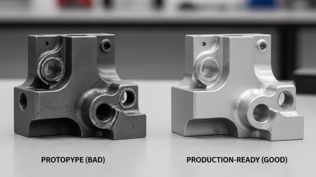
This is where your design decisions have a massive impact. One of the most common and costly “hidden” time-killers we see is the R0 internal corner, which has a real impact on CNC cost and time that many engineers underestimate.
In your CAD software, it’s easy to draw a pocket with a perfect 90° internal corner. In a machine shop, this feature is infinitely expensive to mill. Why? Because all our milling tools are round.
To create that “perfect” corner, we have to:
-
First, mill the pocket with the smallest, most fragile tool possible (which is slow).
-
Then, move your part to a completely different, highly specialized machine—an EDM (Electrical Discharge Machine)—to slowly burn that tiny corner out.
That one “forgotten radius” on a non-critical feature just forced a secondary operation, adding a new setup and process, potentially doubling or tripling your part cost.
How We Help You Optimize This
This is a core part of our DFM (Design for Manufacturability) review. When our engineers see an R0 corner, we don’t just add the EDM cost to your quote. We flag it immediately.
You’ll get a free analysis back from us that says, “We noticed the internal pockets have R0 corners. If these are not critical for function, changing them to a 3mm (or 1/8″) radius will allow us to machine this on a 3-axis mill in a single setup, eliminating the costly EDM process. This change alone can lower your part cost significantly.”
Avoid These Common DFM Pitfalls
These design “time killers” are just the beginning. Download our free guide to the 5 Costly DfM Mistakes in CNC Machining to see how many you can fix in your design right now.
Here is a quick checklist to avoid these time-killers before you even ask for a quote:
-
Internal Radii: Can all my internal corners have a radius of at least 3mm (1/8″)?
-
Hole Depth: Are any of my holes deeper than 10 times their diameter?
-
Thin Walls: Do I have any walls thinner than 1mm (or 0.04″) that could cause vibration or require special handling?
Cost Driver #3: The Exponential Impact of Tolerances
Here is the third, and perhaps most misunderstood, factor in machining cost optimization: tolerances. As an engineer, you’re trained to be precise. It’s tempting to apply a tight, uniform tolerance across an entire drawing (like “All features ±0.01mm”) to ensure quality.
This habit, intended to show rigor, is one of the most expensive mistakes you can make.
The relationship between cost and tolerance isn’t linear—it’s exponential, especially when balancing precision and cost for complex features like thin walls.
As tolerances get tighter, the price doesn’t just go up; it multiplies.
As the digital manufacturing experts at Protolabs often point out in their DFM guidelines, “Moving from a standard tolerance (e.g., ±0.1mm) to a tight tolerance (e.g., ±0.025mm) can increase part cost by 2x to 4x.”
Why? Because that tiny number on your drawing dictates our entire manufacturing process:
Tolerance vs. Relative Cost Impact
| Tolerance Tier | Required Process | Relative Cost |
|---|---|---|
| Standard (±0.1mm / ±0.005″) | Standard CNC Machining | 1x (Baseline) |
| Tight (±0.025mm / ±0.001″) | Slow Machining, New Tooling | 3x – 6x |
| Extreme (±0.005mm / ±0.0002″) | Grinding, Lapping, CMM Inspection | 10x – 20x |
But there’s another hidden cost. When a supplier receives a drawing covered in unnecessary tight tolerances, it’s a red flag. It signals that the designer may not understand DFM, which means they are a “high-risk client.”
We anticipate debates over non-critical features and potential rejections. To protect ourselves, we add a 15-30% “Risk Assessment Tax” to the quote.
We had a new medical device client who learned this the hard way—a potential $50,000 mistake. The engineer had set a global tolerance of ±0.01mm in his CAD template. When he sent us the complex housing, our quote was justifiably high. His purchasing department was furious, claiming a competitor was 40% cheaper.
Instead of just cutting the price, we called the engineer. “These eight decorative chamfers and the engraved logo,” we asked, “do they really need to be held to a tolerance tighter than a human hair?”
He was stunned; it was just a default setting he’d overlooked. He only cared about two O-ring grooves. That’s the difference: the “cheaper” supplier was either going to charge him later or fail the parts. We fixed the drawing with him, marking only the two grooves as critical. The quote dropped by 65%.
How We Help You Optimize This
Stop paying for precision you don’t need. When you send us your drawing, clearly mark your critical-to-function tolerances.
This simple act allows us to focus 100% of our high-end inspection (and your cost) on the features that truly matter. We can then treat the rest of the part as non-critical, saving you a fortune.
If you’re unsure, just send us the file. Our engineers will help you identify and isolate those critical features as part of our free DFM analysis.
Stop Getting Quotes. Start Getting Solutions.

As you can see, machining cost isn’t a “black box” at all. It is the direct and predictable result of every decision you, the engineer, make during the design phase.
The costly “design-quote-redesign” loop only happens when you are forced to work with suppliers who just give you a number. You deserve more than that. You deserve a partner who engages with your design to find the most efficient path to a functional part.
Other suppliers will just send you a price. We, on the other hand, will send you back a value proposal—one that includes a complete, free DFM optimization analysis.
Before you commit to a production run, let’s solve the cost problem together.
Upload your CAD model to our secure portal today to receive your free, no-obligation DFM analysis report. Let our engineers help you identify and eliminate 90% of these potential cost traps before the first chip of metal is ever cut.
Stop wasting time on redesigns. Let us be your technical partner, not just your supplier, and achieve true machining cost optimization from the start.
References & Notes
[1] On Tolerances and Cost: The 2x-4x cost increase for tighter tolerances, as mentioned in the article, is a widely cited rule of thumb in DFM (Design for Manufacturability) resources, such as those published by manufacturing services like Protolabs. This cost increase is due to slower machine speeds, increased tool wear, secondary processes (e.g., grinding), and advanced CMM inspection requirements.
[2] Machinability Rating: This is a standard industry metric, typically benchmarking the machinability of a metal against AISI 1212 carbon steel (which has a rating of 100%). A higher number means the material is easier to machine, allowing for faster cutting speeds and longer tool life, thus reducing machining time and cost.