Tired of your 5-axis designs resulting in sky-high quotes and endless manufacturing revisions? This guide provides a proven Design for Manufacturability (DFM) framework to help you design cost-effective, high-quality parts from the very start. We’ll show you exactly how to leverage single setup machining and avoid common design traps.
Optimizing parts for 5-axis CNC machining involves designing for single-setup manufacturing to improve accuracy, managing geometry like corner radii and wall thickness to suit standard tooling, ensuring features have clear tooling access, and designing explicit workholding surfaces to reduce fixture costs and cycle times.
But there’s more to it than just geometry.
We’ll break down the specific data, real-world case studies, and advanced strategies—like communicating manufacturing intent—that separate an average design from a highly profitable one.
Let’s dive in.
Why 5-Axis Design Isn’t ‘3-Axis+2’
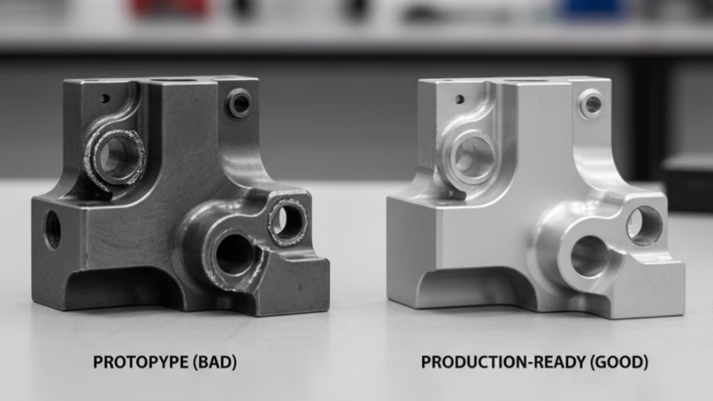
The first and most crucial step in mastering 5-axis design is to fundamentally shift your thinking. Many engineers new to 5-axis machining make the mistake of approaching it with a 3-axis mindset, simply adding two more axes to their existing design process. This is a recipe for inefficiency and high costs.
3-axis machining forces you to think in layers, like building a wedding cake. You’re constantly considering the depth of pockets and the reach of your tools from a single, vertical direction.
5-axis machining, on the other hand, requires you to think in terms of vectors. Instead of asking “How deep can I go?”, you should be asking “From which angles can the tool access this feature?”.
This shift from a Z-axis-centric approach to an omnidirectional one unlocks two powerful advantages:
- Part Consolidation: With the ability to access a part from multiple angles, you can often combine several components into a single, more complex part. This reduces the need for assembly, lowers the overall weight, and eliminates potential points of failure. As lean design expert Sandy Munro often says:
“The best part is no part. The second-best part is one that integrates the function of many.”
- The “Single Setup” Holy Grail: By carefully planning your design, you can often machine all the features of a part in a single setup. This not only saves a significant amount of time but also eliminates the tolerance stacking that can occur when a part is repeatedly re-fixtured. A single setup ensures the highest possible accuracy and repeatability.
A Quantifiable Look at Your Design Decisions
Every decision you make during the design phase has a direct and quantifiable impact on the final cost of your part. Understanding these cost drivers is essential for making informed choices that will lead to a more economical design.
Let’s break down the three main pillars of cost when optimizing designs for 5-axis:
- Pillar 1: Programming and Setup Costs: Before a single chip is cut, a significant amount of work goes into programming the machine and setting up the fixture. This is a fixed cost, meaning it’s the same whether you’re making one part or a hundred. For a complex 5-axis part, this can range from $150 to $500 per setup.
- Pillar 2: Cycle Time Costs: The longer it takes to machine a part, the more it will cost. The deflection of a tool is proportional to the cube of its length-to-diameter ratio (L/D). This means that doubling the L/D ratio increases the tool’s deflection by a staggering eight times, forcing slower machine speeds.
- Pillar 3: Tooling and Fixturing Costs: A client of ours once designed a part with a tiny, 0.5mm radius in a deep pocket. This seemingly insignificant feature required a custom, long-reach tool that was both expensive and fragile, increasing the part cost by nearly 50%. Simply changing the radius to a more standard 2mm could have saved both time and money.
Key Cost Drivers in 5-Axis Machining
| Design Decision | Primary Cost Driver | Optimization Action |
|---|---|---|
| Adding Setups | Setup Costs | Consolidate into one setup |
| Deep Pockets (High L/D) | Cycle Time | Redesign for shorter tools |
| Tight, Non-Standard Radii | Tooling Costs | Use larger, standard radii |
| Thin Walls | Cycle Time / Scrap Rate | Increase wall thickness |
The 10 Golden Rules of 5-Axis Design: An Actionable Checklist
Now that you understand the mindset and the cost drivers, let’s get into the nitty-gritty. Here are ten actionable rules that you can apply to your designs today to make them more 5-axis friendly.
- Manage Your Radii: As we saw in our case study, small, non-functional radii can be a major cost driver. Unless a sharp corner is absolutely essential for the function of your part, be generous with your radii.
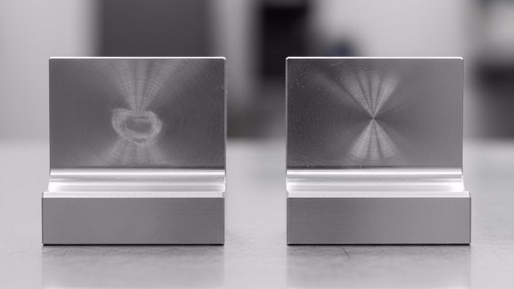
- Control Wall Thickness: Thin walls are prone to vibration and warping. As a general rule, try to keep the wall thickness of your parts above 0.8mm for aluminum and 1.2mm for steel and titanium. Check our CNC wall thickness guide for more details.
- Respect the L/D Ratio: When designing deep pockets or other features that require a long-reach tool, always ask yourself if there’s a way to redesign the part to allow for a shorter, more rigid tool.
- Design “Swarfable” Surfaces: Swarf machining is a highly efficient 5-axis technique. To take advantage of this, try to design your parts with smooth, continuous surfaces that can be easily machined with the side of the tool.
- Consolidate Parts Intelligently: While part consolidation can be a great way to reduce assembly time, there are times when it might actually be more cost-effective to split a complex part into two or more simpler components.
- Design for Tool Access: Always keep the size and shape of the cutting tool in mind. Avoid deep, narrow pockets and other features that are difficult for a tool to access.
- Design for Fixturing: This is a big one. We once had a client who designed a perfectly symmetrical part that was a nightmare to fixture. By simply adding a small, non-symmetrical tab, we could have used a standard vise, saving time and money. Learn more in our guide to 5-axis workholding.
- Standardize Your Features: Whenever possible, try to use standard hole sizes, thread forms, and other features. This allows the machine shop to use their existing tooling.
- Allocate Tolerances Wisely: Unnecessarily tight tolerances can be a major cost driver. You should only specify tight tolerances for the critical features essential for the function of your part.
- Eliminate Unnecessary Features: Before you finalize your design, take a close look at every feature and ask yourself if it’s truly necessary. As Dr. Geoffrey Boothroyd, the father of DFMA, famously said:
“Approximately 70% to 80% of the final cost of a product is determined by the decisions made in the early stages of design.“
Ready to Leverage Full 5-Axis Capabilities?
Our advanced 5-axis machining centers are ready to handle your most complex components. Let our DfM experts help you optimize your design for performance and cost.
Communicating Manufacturing Intent to Eliminate Hidden Costs
A perfect drawing does not guarantee a perfect part. One of the biggest sources of waste comes from the “invisible factory”—the assumptions your supplier has to make when they don’t fully understand your design intent.
This is where communicating your “manufacturing intent” comes in. It’s a simple but powerful way to bridge the gap between design and manufacturing, turning your supplier into an active partner.
The key is to create a simple “manufacturing intent” note to accompany your drawings. Here’s what you should include:
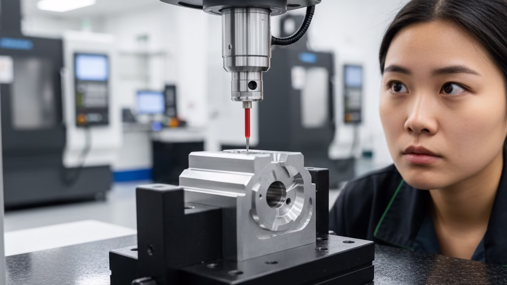
- Identify Critical vs. Non-Critical Features: Use your note to clearly identify the handful of features that are absolutely critical for the function of your part, like a tight-tolerance bore for a bearing.
- Provide Context: A little context can go a long way. For example, “This surface will be in contact with an O-ring, so it’s more important that it’s free of scratches and tool marks than that it’s perfectly flat.”
By taking a few extra minutes to communicate your manufacturing intent, you can save yourself hours of headaches down the road. You’ll get better parts, lower costs, and a much more collaborative relationship with your CNC machining supplier.
The ‘Supplier and Volume’ Matrix
The “best” design is a moving target that depends on two critical variables: who is making your part, and how many are you making?
- The Supplier Reality: “3+2” vs. “Full 5-Axis”: Not all 5-axis machines are created equal. The vast majority are used for “3+2” machining, where the rotary axes position the part for a standard 3-axis operation. “Full 5-axis” or “simultaneous” machining is a more complex and expensive process. Understand the difference with our 3-axis vs 5-axis comparison.
- The Volume Conundrum: When to Consolidate, When to Split:
- For prototypes and small production runs (1-50 pieces), part consolidation is king.
- For larger production runs (1000+ pieces), the equation changes. It might be more cost-effective to split a complex part into two or more simpler components that can be machined in parallel.
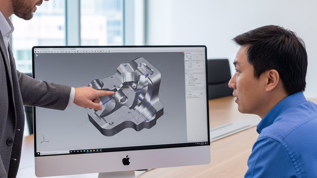
The ultimate strategy is to have a “pre-quote dialogue” with your supplier. Engage with them when your design is about 70% complete to get their expert feedback before you’ve invested too much time.
Conclusion: From Part Designer to Product Value Architect
Mastering Design for Manufacturability for 5-axis machining is about more than just creating cost-effective parts; it’s about elevating your role from a component designer to a true architect of your product’s value.
This knowledge empowers you to not only avoid costly mistakes but to proactively create more innovative, efficient, and reliable products. It transforms you from a passive participant in the manufacturing process to its key driver.
References & Notes
[1] Dr. Geoffrey Boothroyd & DFMA®: The principle that 70-80% of product costs are determined during the design phase is a core tenet of the Design for Manufacture and Assembly (DFMA®) methodology, originally developed by Dr. Geoffrey Boothroyd and Dr. Peter Dewhurst. Their company, Boothroyd Dewhurst, Inc., continues to be the leading authority on the subject.
[2] Sandy Munro & Lean Design: Sandy Munro is a world-renowned expert in lean design and competitive product benchmarking. His philosophy emphasizes part consolidation and simplification as a primary means of reducing manufacturing cost and complexity, a principle widely adopted in the automotive and aerospace industries.