Struggling with high manufacturing quotes and endless design revisions for your CNC turned parts? This no-fluff guide gives you a practical, field-tested DfM checklist. We’ll show you exactly how to optimize your design to significantly cut costs and accelerate your production timeline.
Design for Manufacturability (DfM) for CNC turned parts is the process of proactively designing components to be produced in the most efficient and cost-effective way. This involves optimizing key design elements such as tolerances, material selection, surface finish, and geometric features like corner radii and wall thickness to align with standard CNC turning and lathe capabilities, thereby minimizing machining time and reducing waste.
Now that you know the basics, it’s time to dive into the practical strategies. Keep reading to see real-world case studies, specific cost-saving data, and the 10 golden rules you can apply to your next design.
Why DfM is Your Career’s “Secret Weapon”
Before we dive into the specific rules and checklists, let’s address a crucial point: mastering DfM is one of the most powerful things you can do for your career.
It’s not just about making parts cheaper; it’s about fundamentally increasing your value as an engineer.
Think about it this way: How much of a product’s final cost do you think is determined during the design phase? You might be surprised.
According to Dr. Geoffrey Boothroyd, a pioneer in the field, the decisions you make at your CAD station lock in a staggering 70-80% of the final manufacturing cost.
The choices regarding materials, tolerances, and geometry have a far greater financial impact than any optimization that can happen on the factory floor.
Now, consider the flip side. What’s the cost of getting it wrong? In North America, a single, mid-complexity design revision can create $1,000 to $5,000 in associated costs.
That figure includes not just your time, but the time of procurement managers, the cost of project delays, and the potential for scrapped materials. When you view DfM through this lens, it transforms from a simple best-practice into a critical risk management strategy.
By investing a little extra time upfront, you are actively preventing significant financial and temporal losses down the line, protecting your project and your reputation.
The Three Pillars of Cost: A Quantified Approach
To make smart DfM decisions, you need to understand where the costs are actually coming from. It’s not magic; it’s a predictable result of your design choices.
Let’s break it down into three pillars that have the biggest impact on the final price when optimizing for CNC turning.
Pillar 1: Tolerances and Surface Finish
This is often the biggest and most overlooked cost driver. There’s a natural tendency to specify tight tolerances “just in case,” but that caution comes with a steep, exponential price tag.
- Standard Tolerance (e.g., ±0.1 mm / ±0.005″): 1x (Baseline Cost)
- Precision Tolerance (e.g., ±0.025 mm / ±0.001″): 1.5x – 2x the cost
- Ultra-Precision Tolerance (e.g., ±0.005 mm / ±0.0002″): 3x – 5x the cost (or more)
The same principle applies to surface finish. Moving from a standard machined finish (Ra 3.2 μm) to a fine finish (Ra 1.6 μm) or a ground finish can easily double the cost. For a deeper look at how this impacts your budget, see our guide on Ra 0.8μm vs. Ra 0.4μm finishes.
The key takeaway? Design for function, not for habit.
Before specifying a tight tolerance, ask yourself: is this absolutely critical for the part’s function, like a bearing fit or a sealing surface? If not, use a standard tolerance. You’ll save a significant amount of money without sacrificing performance.
Pillar 2: Material Selection
Choosing a material based solely on the raw material cost is a classic trap. The true cost of your material is a combination of its price and its machinability.
A cheaper material that is difficult to machine can easily result in a more expensive final part.
Consider this estimated comparison, using Aluminum 6061 as a baseline:
| Material | Raw Material Cost Index | Machinability Rating | Total Machining Cost Index |
|---|---|---|---|
| Aluminum 6061-T6 | 100 | 100% | 100 (Baseline) |
| Brass 360 | 180 | 300% | ~150 |
| Stainless Steel 304 | 250 | 45% | ~400 |
| PEEK | 1500 | 50% | ~2000 |
As you can see, even though brass is more expensive per kilogram than aluminum, its incredible machinability can make it a more cost-effective choice for complex parts. Conversely, the difficulty of machining stainless steel significantly increases the total cost.
Pillar 3: Batch Size and Setup Costs
Finally, it’s crucial to understand the economics of production volume. The price of a single part is determined by this simple formula:
Unit Price = (Setup Cost / Batch Size) + Unit Part Cost
The “Setup Cost” includes everything from programming the CNC machine to preparing the tooling and performing the first-article inspection. This is a fixed cost, typically ranging from $150 to $500.
If you order one prototype, that single part bears the entire setup cost. If you order 1,000 parts, the setup cost is spread so thin it becomes almost negligible. This is why prototyping is inherently more expensive per piece and why designing for an efficient, single-setup operation is so important.
Need High-Quality CNC Turned Parts?
From simple shafts to complex components, our advanced CNC turning services deliver parts with the precision and quality your project demands. Let our experts bring your designs to life.
10 Golden Rules for Optimizing Your CAD Model

Now that you understand the principles, let’s get to the practical application. This checklist is your guide to creating cost-effective and manufacturable CNC turned parts.
Think of these as the golden rules to follow before you export that final STEP file.
- Embrace Standard Corner Radii
Sharp internal corners are a machinist’s nightmare. A standard turning insert has a radius, making a true 90-degree internal corner impossible without special (and expensive) processes.- Do: Design internal corner radii to be at least R0.8mm (0.031″). This allows the use of standard, robust tooling.
- Respect the Length-to-Diameter Ratio
Drilling deep, narrow holes is a high-risk operation. The deeper you go relative to the diameter, the harder it is to clear chips, leading to tool breakage and inaccurate holes.- Do: Keep the length-to-diameter ratio (L:D) of any hole below 10:1. If you must go deeper, consult with your manufacturer about specialized solutions.
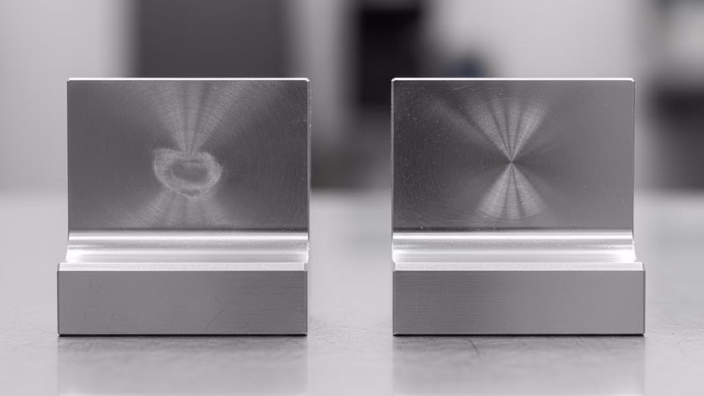
- Maintain Minimum Wall Thickness
Extremely thin walls are prone to vibration and distortion during machining. This forces the machinist to slow down, increasing cycle time, and can lead to parts that are out of tolerance.- Do: For metals like aluminum and steel, design for a minimum wall thickness of 0.8mm (0.030″). For a full breakdown, check our CNC Wall Thickness Guide.
- Design for Standard Threads
Custom threads require custom, expensive tooling. Standard threads (like M6 or 1/4-20) are machined with common taps and dies, which is always cheaper and faster.- Do: Always use standard thread sizes and ensure you design a proper undercut or relief groove at the end of the thread. This gives the tool a place to exit, ensuring a complete and clean thread.
- Simplify Geometry
As lean design expert Sandy Munro states,“complexity is the enemy of manufacturing.”
Every extra feature, groove, or pass adds time and cost.
- Do: Constantly ask yourself: Is this feature absolutely necessary for the part’s function? If not, remove it.
- Use Standard Drill Sizes
Just like with threads, it’s always better to design holes that correspond to standard, off-the-shelf drill bit sizes.- Do: Instead of a 10.35mm hole, consider if a standard 10.5mm or even 10.0mm hole would function just as well.
- Ensure Tool Accessibility
If a cutting tool can’t reach a feature, it can’t be machined. This is especially true for complex internal geometries or deep grooves.- Do: Visualize the path a cutting tool would take. Ensure there is clear access for the tool and its holder to approach and cut every feature.
- Integrate vs. Assemble
Sometimes, it’s cheaper to combine two simple parts into one more complex part to save on assembly costs. Other times, it’s better to break a very complex part into two simpler components.- Do: Evaluate the trade-offs. Consider if simplifying the machining of individual components outweighs the cost and complexity of a secondary assembly step.
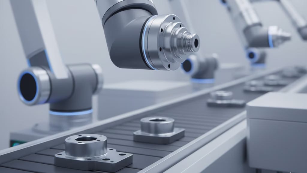
- Design for Automation
Modern manufacturing relies on automation. Features that make a part easy for a robot to grab and orient can significantly reduce handling costs.- Do: Could adding a small flat to a cylindrical part allow a robotic gripper to hold it more securely? This small design consideration can have a big impact on high-volume production.
- Communicate Your Intent
This is perhaps the most crucial rule. Your drawing should not just be a set of dimensions; it should communicate your design’s purpose. More on this later.
| Common Design Flaw | Impact | Solution |
|---|---|---|
| Sharp Internal Corners | Requires costly EDM/special tooling. | Add radius ≥ R0.8mm. |
| Overly Tight Tolerances | Exponential cost increase (3x-5x). | Specify only where functionally critical. |
| Deep, Narrow Holes (L:D > 10:1) | High risk of tool breakage, slow process. | Redesign or consult manufacturer. |
| Thin Walls (< 0.8mm) | Vibration, distortion, poor finish. | Increase thickness, add supports. |
Two Hard-Earned Lessons from the Shop Floor
The rules and data we’ve discussed are powerful, but sometimes the most memorable lessons are the ones learned the hard way.
To show you just how critical these DfM principles are, we want to share two stories from our own experience—moments where a seemingly perfect design collided with the physical realities of manufacturing.
The “Perfect Drawing” Cost Trap
We once received a drawing from a meticulous client that was, by all academic standards, flawless. Every single dimension was toleranced to an incredibly tight ±0.01mm, and the entire part required a mirror-like surface finish. It was a beautiful piece of technical documentation.
The problem? Our quote was 2.5 times their budget.
The client was understandably shocked. But instead of debating the price, our lead engineer asked a simple question: “Which features on this part are actually doing the work?”
It turned out that out of dozens of dimensions, only two were truly critical: an inner diameter for a bearing press-fit and a single flat face for a seal. Over 80% of the tightly-toleranced features were non-functional.
The Lesson: A perfect drawing does not equal a perfect design. The goal is to be fit for purpose. We revised the drawing to hold tight tolerances only on the two critical features and applied a standard, cost-effective finish to the rest.
The result? A 45% cost reduction with zero impact on the part’s performance. Always challenge your own assumptions and distinguish between “functional requirements” and “habitual over-engineering.”
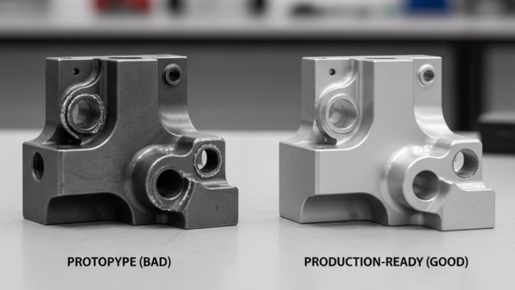
The “Simple Material Swap” Nightmare
Another time, a startup client had a successful prototype built from Aluminum 6061. For the production version, they wanted to upgrade to 316L Stainless Steel for better durability. In the CAD software, this was a simple change in the material properties. In reality, it was a disaster waiting to happen.
When we started the first small production run, the problems cascaded. The work-hardening nature of 316L stainless steel destroyed cutting tools at an alarming rate.
More critically, a key thin-walled feature on the part, which was stable in aluminum, warped and distorted under the high stress of machining stainless steel. Our scrap rate soared to an unsustainable 40%.
The Lesson: Material and geometry are inextricably linked. You cannot change one without re-evaluating the other. We had to pause production and work with the client to re-design the part specifically for stainless steel.
By increasing the thickness of the problematic wall by just 0.5mm—a change that didn’t affect the final assembly—we brought the scrap rate down to under 5% and saved the project. Never assume a design is portable across different materials.
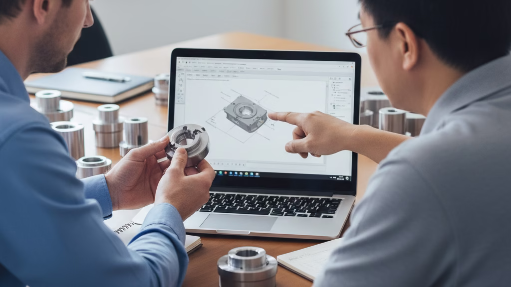
Communicating “Manufacturing Intent” to End Hidden Costs
Here is a concept that can fundamentally change the relationship you have with your manufacturer: the most significant hidden costs in machining don’t come from the physical act of cutting metal.
They come from the “invisible factory”—the time wasted in guesswork, clarification emails, and the over-machining of non-critical features.
Your technical drawing is a precise set of instructions, but it’s a document without context. The machinist on the shop floor can see what to make, but they have no idea why. They don’t know which surface is a critical seal, which diameter is a running fit, and which face is purely for aesthetics.
Lacking this crucial information, they are forced to assume every feature is critical, meticulously machining every surface to the highest possible standard to protect themselves. This is a massive, hidden cost-driver.
The solution is surprisingly simple yet incredibly powerful: supplement your drawing with a short “Key Functions & Manufacturing Intent” document.
This isn’t a long report; it’s a few bullet points that give your drawing a purpose.
For example:
- “Dimension A (Ø20mm, h6 tolerance): This is the most critical dimension. It is a press-fit for a standard XXX bearing.”
- “Surface B (Ra 0.8): This is a dynamic sealing surface. Freedom from scratches is more important than absolute flatness.”
- “All other features: These are non-functional. Please adhere to standard shop tolerances to optimize for cost.”
This simple act of communication transforms the entire process. You empower the machinist with the expert knowledge they need to make smart decisions.
They can now focus their time and energy on what truly matters, applying more efficient techniques to the non-critical areas. This single step eliminates guesswork, reduces cycle time, and turns your supplier from a simple order-taker into a true manufacturing partner.
Conclusion: Becoming a More Valuable Engineer
Mastering Design for Manufacturability is more than just a technical skill; it’s a fundamental shift in your approach as an engineer.
As we’ve explored, it’s a mindset that empowers you to look beyond the geometry on your screen and understand the real-world consequences of your design decisions. By embracing these principles, you move from being a designer of parts to being an architect of successful, profitable products.
You now have a framework to control costs, mitigate risks, and collaborate more effectively with your manufacturing partners. The result is not only a better final product—one that is more reliable, cost-effective, and quicker to market—but also an increase in your own professional value.
You become the engineer who can be trusted to deliver designs that work, on time and on budget.
But theory is only the first step. If you’re looking at a design right now and wondering how these principles apply, we want to help.
References & Notes
[1] The 80/20 Rule in Manufacturing Costs: The principle that 70-80% of a product’s manufacturing cost is determined by its design phase is a foundational concept in DFMA, widely attributed to the research of Dr. Geoffrey Boothroyd and his colleagues.
[2] Work Hardening (Strain Hardening): This is a phenomenon where a metal becomes stronger and harder as it is plastically deformed. In austenitic stainless steels like 316L, this process is particularly pronounced and can involve the transformation of austenite to martensite, significantly increasing machining difficulty.