Tired of unpredictable tool failures and costly scrapped parts when machining hardened steels like D2 and A2? This is the no-fluff, actionable guide you’ve been looking for. We provide a proven, step-by-step system that eliminates the guesswork so you can achieve stable, predictable, and profitable results every time.
Successful machining of hardened steels (55-65 HRC) requires a systematic approach. The process involves selecting the correct cutting tool, typically Cubic Boron Nitride (CBN), and using a strategy of high cutting speeds (100-200 m/min) with light depths of cut. Employing modern CAM toolpaths to ensure constant tool engagement and a highly rigid setup with minimal tool runout are critical for preventing tool failure and achieving a superior surface finish.
Now that you know the core principles, read on to get the detailed starting parameters, advanced troubleshooting guides, and cost-benefit templates you need to implement this strategy flawlessly.
Strategy: Winning Before You Begin
Break the ‘Single-Point’ Mindset: The Process Chain
When a tool fails, our first instinct is often to blame the tool itself or the cutting parameters. This is a classic example of “single-point thinking.”
The reality is that success in hardened steel machining is determined by a series of interconnected links, what we call the “process chain.” A failure in any one link can cause the entire operation to collapse. Think of it as a literal chain: it’s only as strong as its weakest link.
This chain starts long before the tool ever touches the metal. It begins with heat treatment. You might see “60 HRC” on a spec sheet and assume the workpiece has uniform hardness. This is a critical and often incorrect assumption.
Non-uniform heat treatment can create invisible hard spots that act like landmines for your cutting tool, causing it to chip or break unexpectedly. Before you even begin machining, have a conversation with your heat treatment supplier.
Understand their process and stress the need for uniformity, a principle covered in detail within this guide to heat treatment distortion control.
The next, and perhaps most underestimated, link in the chain is your tool holding system. You can invest in the most advanced, expensive cutting tool on the market, but if you clamp it in a standard, worn-out tool holder, you’ve completely undermined its potential.
It’s like fitting a Formula 1 car with budget tires and then wondering why it can’t perform. For the rigidity and precision required in hard milling, high-quality holders like shrink-fit or hydraulic chucks are not luxuries; they are essential components of a stable process.
Make the Smartest Route Choice: Hard Milling vs. Hard Turning vs. Grinding
Before you get lost in the details of speeds and feeds, take a step back and look at the bigger picture: is your chosen machining method the best strategic fit for the job?
We often get locked into one way of doing things, but top-tier engineers know when to re-evaluate the entire process route. The three primary methods for finishing hardened components are hard milling, hard turning, and grinding.
Each has distinct advantages, and the optimal choice depends entirely on your specific goals for efficiency, cost, and quality. For features involving sharp internal corners or geometries too delicate for cutting tools, the evaluation must also include non-contact methods, requiring a thorough EDM process comparison to make the final decision.
Grinding has long been the standard for achieving the highest precision and finest surface finishes, capable of reaching below Ra 0.1 μm. However, it is typically a slower process that requires specialized equipment.
This is where hard turning presents a compelling alternative. For many applications, the efficiency gains are substantial. With modern CBN tooling, hard turning can achieve excellent surface finishes (down to Ra 0.2 μm) and tight tolerances.
This is all while reducing cycle times by as much as 50% to 70% compared to grinding. This is because it is often more flexible and can combine multiple operations in a single setup on a standard CNC lathe, drastically reducing total lead time. The choice isn’t just about technical capability; it’s about the overall business impact.
Tactical Prep: Equipping Your Arsenal
Know Your Materials: D2 and A2 Steel
Before you can select the right tools, you need a clear understanding of what you’re up against. D2 tool steel, with its high carbon and chromium content, is known for its exceptional wear resistance. It typically has a working hardness of 58-62 HRC.
This same property that makes it so durable also makes it challenging to machine. On the other hand, A2 tool steel is an air-hardening steel that offers a better balance between wear resistance and toughness, usually sitting in the 57-60 HRC range. It is generally a bit more forgiving to machine than D2, but both demand a systematic approach.
A Systematic Approach to Tool Selection
Choosing the right cutting tool is the most critical tactical decision you will make. Instead of relying on guesswork or old habits, you need a structured framework.
The optimal tool depends on three key factors: the workpiece hardness, the tool material, and the specific machining conditions (such as continuous vs. interrupted cuts).
Here’s a breakdown of your primary tool material options:
- Coated Carbide: For hardness levels between 45-55 HRC, modern coated carbide tools are an excellent and cost-effective choice. Look for advanced coatings with high aluminum content, such as TiAlN or AlCrN, which provide the necessary heat resistance.
- Ceramics: In the 55-65 HRC range, ceramic tools can achieve very high cutting speeds, sometimes up to 300 m/min, making them great for high-volume finishing operations. However, they are extremely brittle and require a highly rigid machine and stable setup.
- Cubic Boron Nitride (CBN): This is the mainstream choice for machining materials in the 55-65 HRC range and is particularly effective for finishing operations. CBN offers a superb combination of hot hardness and toughness, leading to excellent tool life and superior surface finishes.
However, simply choosing “CBN” is not enough. As the experts at Sandvik Coromant emphasize:
“The choice of CBN grade is critical and depends on the application’s demands for toughness versus wear resistance. A high CBN content grade is tougher and better suited for…interrupted cuts. Conversely, a low CBN content grade with a ceramic binder offers higher hot hardness and superior wear resistance, making it ideal for continuous finishing operations.”
Using the wrong grade is a common and costly mistake.
Essential Supporting Systems: Clamping and Cooling
Finally, remember that even the best cutting tool will fail without the right support. Your clamping strategy must be robust to prevent any micro-vibrations, which are fatal in hard milling.
This reinforces the importance of using high-quality hydraulic or shrink-fit tool holders. When it comes to cooling, the strategy may be counterintuitive.
For many hard milling operations, particularly with CBN or ceramic tools, a continuous blast of coolant can cause thermal shock, leading to micro-cracks in the tool. In these cases, dry machining or using a minimal quantity lubrication (MQL) system is often the superior approach, using a directed air blast to clear chips.
Master Hard Material Machining
Your project demands precision in the toughest materials. Our advanced CNC grinding and wire EDM services deliver the accuracy and surface finish that standard milling can’t achieve. Let’s tackle your most demanding components.
Execution: The Core Playbook
With your strategy set and your tools selected, it’s time to execute. This section is the heart of the playbook, providing the specific tactical information you need to program your machines with confidence.
We’ll break down the two primary processes—hard milling and hard turning—into actionable steps and starting parameters.
Hard Milling Playbook
Successful hard milling is a game of finesse, not brute force. The core strategy is to use light depths of cut at high speeds and feeds to maintain a consistent, manageable load on the cutting tool.
| Operation | Tooling Example | Cutting Speed (Vc) | Feed per Tooth (fz) | Axial DOC (ap) | Radial DOC (ae) |
|---|---|---|---|---|---|
| Face Milling (Roughing) | Coated Carbide Insert | 70-100 m/min | 0.12-0.20 mm/t | 0.3-0.5 mm | 50-75% of Diameter |
| Contour Milling (Finishing) | Solid Carbide Ball End Mill | 120-180 m/min | 0.10-0.18 mm/t | 0.1-0.2 mm | 0.1-0.2 mm (Stepover) |
| Corner Finishing | Small Diameter Ball End Mill | 100-150 m/min | 0.05-0.10 mm/t | 0.05-0.1 mm | 0.05-0.1 mm (Stepover) |
Disclaimer: These are starting points. Always begin conservatively (around 80% of these values) and optimize based on your specific machine, toolholder, and setup.
Advanced CAM Toolpaths Are Non-Negotiable
Simply plugging in the right numbers is not enough. Your programming strategy is just as crucial as the cutter itself.
As Mike Mattera, a respected expert from MoldMaking Technology magazine, points out, “You must use modern toolpaths like trochoidal milling or peel milling to maintain a constant tool engagement angle and a consistent chip load. A straight-line path that slams the tool into a corner is a recipe for disaster.”
Conventional toolpaths create sudden spikes in tool load, especially in corners, which is the primary cause of tool failure in hard materials. Modern CAM strategies are designed to prevent this:
- Trochoidal Milling: Uses a circular, peeling motion to create a channel, ensuring the tool is never “buried” in the material.
- Contour (High-Speed) Machining: Maintains a consistent stepover and smooth, arcing movements, eliminating sharp, jarring turns.
Hard Turning Playbook
Hard turning is an incredibly efficient process for finishing cylindrical parts, but it requires attention to the unique pressures involved.
| Operation | Tooling Example | Cutting Speed (Vc) | Feed Rate (fn) | Depth of Cut (ap) |
|---|---|---|---|---|
| Continuous Finishing | Low-Content CBN Insert | 120-180 m/min | 0.05-0.12 mm/rev | 0.1-0.25 mm |
| Interrupted Cutting | High-Content CBN Insert | 90-140 m/min | 0.08-0.15 mm/rev | 0.15-0.3 mm |
The Critical Role of Insert Geometry
In hard turning, the geometry of the CBN insert is designed for strength. You will almost always use an insert with a negative rake angle. This directs the immense cutting forces down into the tool holder and the machine, rather than trying to “lift” the chip.
This would put the delicate cutting edge under tensile stress. Furthermore, the cutting edge will often have a small chamfer or hone (known as a K-land) to make it more robust and prevent chipping. Understanding and selecting the correct geometry is fundamental to success.
Optimization & Troubleshooting: Becoming the Go-To Problem Solver

Even with the best plan, things can go wrong. This is where a good engineer becomes a great one. Instead of randomly adjusting parameters, you need a systematic approach to diagnose and solve problems.
This section is your emergency guide for when the unexpected happens.
A “First-Aid” Guide for Common Machining Issues
When a problem arises, don’t just change the feed rate and hope for the best. Work through a logical diagnostic sequence. Think of it as a checklist, moving from the easiest things to check (the code) to the more complex (the machine itself).
| Problem | Primary Checks (In Order) | Potential Solutions |
|---|---|---|
| Chatter (Vibration) | Tool Overhang > Toolpath > Clamping | Shorten tool; Use constant-engagement path; Check holder & workpiece rigidity. |
| Premature Tool Wear | Cutting Speed > Chip Load > Tool Grade | Reduce Vc; Adjust fz to avoid rubbing; Verify correct insert for the job. |
| Poor Surface Finish | Semi-Finish Stock > Tool Wear > Runout | Ensure uniform stock allowance; Use fresh tool edge; Check tool holder runout. |
Lessons Learned the Hard Way: Our Experience
Theories and charts are one thing, but some lessons are only learned through costly real-world experience. Here are two critical lessons we’ve learned that we want to share with you.
Experience 1: The Trap of Chasing Maximum Speed
We once worked with a client who programmed the absolute maximum cutting speed from a technical manual for a D2 mold component. The result was a disaster. Halfway through the first pass, the insert shattered, destroying itself and the expensive workpiece along with it.
The lesson here is profound: stability is far more important than maximum speed. Our sincere advice is to always start at 70-80% of the manufacturer’s recommendation. Once the process is stable, you can gradually increase parameters to find the optimal “sweet spot” for your specific machine and setup.
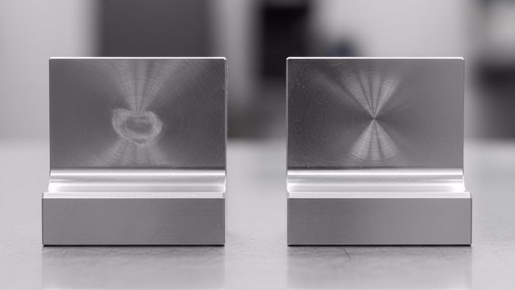
Experience 2: The Secret to a Perfect Finish
Another common frustration is an inconsistent surface finish. We once spent days troubleshooting a job where some areas were mirror-perfect while others had visible tool marks. We adjusted every conceivable finishing parameter to no avail.
The problem was rooted in the semi-finishing operation. A large step-over had been used, which left an uneven amount of stock for the finishing tool. This fluctuation in tool load was the cause of the inconsistent finish.
The solution is to add a rule to your process: ensure the stock left for finishing is uniform and consistent, ideally within a tight band like 0.15 mm ±0.03 mm. This small investment in the semi-finishing stage will pay huge dividends in the quality of your final part.
Value Justification: Making Your Case
As an engineer, your technical expertise is your greatest asset. However, to get approval for new tools or processes, technical merit alone is often not enough. You need to speak the language of business: money.
This final section is about empowering you to build an undeniable business case for your proposed improvements.
It’s Not Just a Technical Story, It’s a Financial One
When you propose a new solution, decision-makers are asking one fundamental question: “How will this impact our bottom line?” A vague promise of “better efficiency” is not a compelling argument.
You need to translate technical advantages into tangible financial outcomes. Instead of just calculating the cost of a new tool, reframe the conversation around the cost of not changing. Let’s quantify the “hidden costs” that are draining resources right now.
- The Total Cost of a Single Failure: When a tool breaks and scraps a part, the loss is far more than just the price of the insert. The true cost includes the tool, the raw material, all the machine hours already invested, labor for downtime, and potential delivery penalties. Presenting this total number provides a much more impactful picture of the current process’s financial risk.
- The Opportunity Cost of Inefficiency: This is an even more powerful concept. If a new process cuts machining time from 10 hours to 5, you haven’t just saved 5 hours of machine time. You have gained 5 hours of production capacity on a valuable asset. Frame your argument this way: “By investing in this new process, we are not just saving costs; we are creating an opportunity to take on more work and increase our sales.”
Conclusion: From Process Engineer to Process Strategist
We’ve covered a lot of ground, moving from high-level strategy to the nitty-gritty details of execution and troubleshooting. If there’s one central idea to take away from this playbook, it’s the shift in mindset from being a reactive problem-solver to a proactive process strategist.
Success in the machining of hardened steels is not about finding a single “magic number” for your speeds and feeds. It’s about understanding the entire process chain and making deliberate, data-driven decisions at every stage.
It’s about learning from failures and building your own internal database of what truly works on your machines, with your team.
By embracing this holistic approach, you elevate your role. You are no longer just an engineer who executes a plan; you are the architect of a predictable, stable, and highly profitable manufacturing process. You become the go-to expert who can not only solve the immediate technical challenges but also drive the strategic improvements that make your company more competitive.
If you’re facing a unique challenge with the machining of hardened steels that this guide didn’t cover, contact our application engineers. We are always ready to provide one-on-one consultation to help you find a solution.
References & Notes
[1] CBN Grade Selection: The distinction between high-content CBN for interrupted cuts (toughness) and low-content CBN for finishing (wear resistance) is a core principle in cutting tool application, emphasized by leading manufacturers like Sandvik Coromant in their technical literature.
[2] Constant Tool Engagement: The concept that maintaining a consistent load on the cutter is critical for tool life in hard milling is a foundational principle of High-Efficiency Milling (HEM) and is widely discussed by CAM software developers and tooling experts like Mike Mattera.