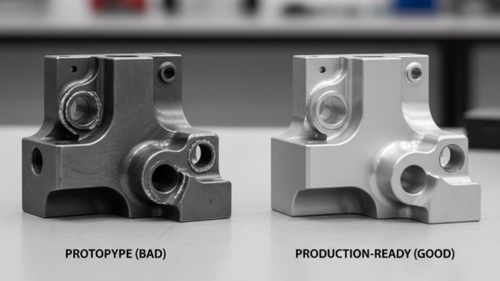
Frustrated by perfect CAD designs turning into warped, expensive scrap metal during CNC machining? This guide introduces the Anti-Fragile Framework, a proven set of DfM rules that transforms design uncertainty into predictable costs and first-time-right parts.
Critical CNC design mistakes involve specifying thin walls that cause machine chatter, designing improper rib-to-wall ratios which create sink marks and stress, and defining sharp internal corners or overly tight tolerances that dramatically increase manufacturing time and cost.
But spotting these individual design flaws is only the first step. What truly separates elite engineers is not just knowing the rules, but using a systematic decision-making framework to balance performance, cost, and manufacturability.
This guide will walk you through that exact framework, providing the quantitative rules and strategic insights needed to move beyond simply avoiding errors and begin designing truly optimized, anti-fragile parts.
Why Do Thin-Walled Parts Destroy Themselves During Machining?
Before we dive into the solutions, it’s critical to understand the forces at play. When you understand the ‘why’ behind the failure, the ‘how’ of the solution becomes intuitive. There are three invisible forces working against your design inside the CNC machine.
Summary: The Three Forces of Machining Failure
| Failure Mode | Root Cause | Primary Consequence |
|---|---|---|
| Part Vibration (Chatter) | Tool frequency syncs with part’s natural resonant frequency. | Wavy surface finish, poor dimensional accuracy. |
| Thermal Deformation | Uneven heat expansion & contraction from cutting forces. | Part bowing, twisting, and internal stress buildup. |
| Clamping Distortion | Part flexes under vise pressure during the machining operation. | Surfaces are not flat or true after the part is released. |
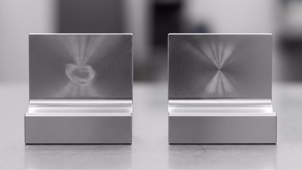
What is “Chatter” and Why Does It Ruin Surface Finish?
Chatter, or self-excited vibration, is the ghost in the machine. Imagine tapping the side of a drum—it vibrates at a specific frequency. Now, imagine a CNC cutting tool, spinning at tens of thousands of RPM, tapping that same drum skin thousands of times per second.
If the frequency of those “taps” aligns with the natural resonant frequency of your thin wall, the wall begins to vibrate violently.
This isn’t random. It’s a feedback loop where the tool’s cutting action excites the part, and the part’s vibration in turn affects the tool’s next cut. The result? A distinctive, wavy pattern of tool marks on the surface and a part that is dimensionally inaccurate.
This is why even the most rigid, high-end machine can produce a poor-quality part if the design itself is prone to vibration.
How Does Thermal Deformation Warp a Perfectly Straight Part?
The process of cutting metal generates an immense amount of localized heat. While coolants help manage this, the effect on thin parts can be dramatic. The key factor here is a material’s thermal conductivity.
Consider aluminum 6061, with a high thermal conductivity (≈205 W/m·K). The heat from the cutting tool rapidly spreads across the entire part. As the thin wall heats up, it expands.
After the cut is complete and the part cools, it contracts, but not always evenly. This thermal cycle introduces internal stresses that can cause a once-flat part to bow or twist.
In contrast, stainless steel has a much lower conductivity (≈16 W/m·K). It traps heat in the cutting zone, which can cause localized hardening and make the material even more difficult to machine, while still posing a risk of distortion.
How Can Clamping Force Bend a Part Before the First Cut?
To be machined, a part must be held absolutely still. This is typically done with a powerful vise or custom fixtures. While necessary, this clamping force itself can be a source of deformation.
Imagine squeezing a plastic water bottle. Even a small amount of pressure will cause the thin walls to deflect. The same happens to your part inside the vise. A thin-walled enclosure can be flexed by just a few microns by the clamping pressure. The machine then cuts this slightly flexed part.
When the machining is finished and the part is unclamped, it springs back to its natural state, but now the machined surfaces are no longer true or flat. For a typical 200x100x2mm aluminum housing,
a clamping misalignment of just 0.1mm can result in a final flatness deviation of over 0.05mm—often enough to fail our rigorous quality control process.
The “Safe Zone”: Quantifiable Rules for Designing Stable Parts
Now that you understand the forces working against you, let’s build your defense. This is your “safe zone”—a set of quantifiable rules and guidelines. Following these won’t just increase your success rate; it will give you the confidence to innovate, knowing your designs are grounded in solid manufacturing principles.
How Thin Can You Actually Machine a Wall?
While it’s tempting to look for a single number, the truth is more nuanced. The absolute minimum wall thickness is not a fixed rule but a dynamic function of material, geometry, and risk. However, we can establish highly reliable guidelines:
| Material | General Minimum (High Success) | Expert Minimum (Requires DFM) |
| Aluminum (6061, 7075) | 1.5 mm (0.060 in) | 0.8 mm (0.030 in) |
| Steel (Stainless, Alloy) | 2.0 mm (0.080 in) | 1.0 mm (0.040 in) |
| Plastics (Delrin, ABS) | 1.5 mm (0.060 in) | 1.0 mm (0.040 in) |
Key Considerations:
- Aspect Ratio is Critical: The most important factor is the wall’s height-to-thickness ratio. A wall with a ratio below 10:1 is generally stable. Exceeding this can dramatically increase machining time and risk.
- A Note on “Hero” Machining: Can a skilled machinist create a 0.5mm aluminum wall? Yes, for a single prototype, under perfect conditions. But this is not a repeatable, production-safe dimension. For production parts where consistency is key, staying within the “General Minimum” is the most cost-effective strategy.
The “Golden Ratio” for Designing Strong Ribs
Ribs are your most powerful tool for adding stiffness without adding significant weight. However, poorly designed ribs can create more problems than they solve, causing sink marks and stress concentrations. Here are the golden rules for effective rib design:
- How thick should a rib be? A rib’s thickness should be 50% to 60% of the wall it is attached to. Making a rib too thick creates a large mass of material that will shrink and cool differently, causing a visible “sink mark” on the opposite side of the wall.
- Formula: Trib = (0.5 to 0.6) × Twall
- How tall can a rib be? The height should be no more than 3 times the nominal wall thickness. Taller ribs become thin-wall features themselves and are prone to breakage or vibration during machining.
- Formula: Hrib ≤ 3 × Twall
- How far apart should ribs be? The space between two ribs should be at least 2 times the nominal wall thickness. This ensures the cutting tool has adequate clearance to machine the channel between them without the walls flexing.
- Formula: Sribs ≥ 2 × Twall
Which Details Have the Biggest Impact on Machinability?
The devil is truly in the details. Small, seemingly minor features often have the largest impact on cost and quality.
The internal corner radius is a huge cost driver. Sharp internal corners cannot be machined with a round tool. You must design a fillet radius. For optimal results, your internal corner radius should be at least 1/3 of the cavity’s depth.
More importantly, as Greg Paulsen of Xometry frequently advises, designing with standard tool radii in mind (e.g., 3mm, 6mm) is one of the easiest ways to reduce machining costs, as it allows the machinist to use common, rigid tools at optimal speeds.
How Can You Think Beyond the Part and Design for the Process?
Following design rules is the foundation of good DFM. But to truly elevate your skill, you need to shift your mindset. Great engineers don’t just design a static object; they mentally choreograph the entire manufacturing process. They design not just the part, but the path to creating it.
How Can You Start to “Think Like a Machinist”
Before you finalize a design, conduct a “virtual process review.” Imagine you are the machinist who has just received your file. What are the first questions you would ask?
- “How am I supposed to hold this thing?” This is the most critical question. Look at your part. Where are the flat, stable, parallel surfaces for a vise to clamp onto? For our drone remote case study, the initial design was all smooth curves, offering no good place for workholding. The solution involved designing the part to be machined from a larger block, leaving a “picture frame” of sacrificial material around the part for clamping, which was removed in the final operation. Sometimes, you may even need to add a temporary feature—a tab or a boss—solely for workholding, to be machined off at the end.
- “Can my tools actually reach that feature?” Your CAD software can create any geometry, but a CNC machine is limited by the physical reach of its cutting tools. Look at deep pockets and narrow channels. Is there enough clearance for a standard-sized end mill? Or are you forcing the use of a long, thin tool that is highly susceptible to deflection and chatter? Widening a channel by a millimeter or increasing a corner radius can make the difference between an efficient process and a risky, expensive one.
Why is Your Material More Than Just a Color in CAD
As we saw with thermal deformation, material properties are not abstract data points; they have profound real-world consequences. A strategic designer leverages these properties instead of fighting them.
Think about the difference in thermal conductivity between aluminum and stainless steel again. When designing a thin-walled aluminum part that will undergo heavy machining, you can anticipate the heat buildup.
This might lead you to design in features that act as heat sinks or to specify a multi-stage machining process where the part is rough-machined, then allowed to cool and stabilize before the final finishing cuts are made.
This is a level of process-aware design that prevents costly surprises and demonstrates true expertise to your manufacturing partner.
How Do Your Design Decisions Directly Impact the Final Cost?

As an engineer, you are not just a technical professional; you are a steward of project resources. Every decision you make in CAD has a direct and often dramatic impact on the final part cost.
Understanding this relationship empowers you to make smarter trade-offs and to confidently justify your design choices to managers and procurement teams.
How Can a 0.1mm Tolerance Change Double Your Machining Cost?
The connection between design features and cost isn’t always linear. Certain features are “cost multipliers” that can exponentially increase machining time.
- The Price of Precision: A standard machining tolerance might be +/- 0.1mm. Tightening that to +/- 0.05mm might increase the cost of that feature by 50%, as it may require slower cutting speeds and additional inspection steps. Tightening it further to +/- 0.025mm could easily double the cost, potentially requiring specialized finishing processes like precision grinding or lapping. Always ask: “Does this feature truly require this level of precision for its function?”
- The Cost of a “Perfect” Corner: As mentioned, avoiding a standard corner radius is a classic cost multiplier. If your design requires a sharp internal corner of R=0.2mm, a standard end mill cannot create it. This single feature might necessitate a completely separate operation on an EDM (Electrical Discharge Machining) machine, adding hundreds of dollars and days of lead time to your project.
- The Deep Pocket Dilemma: The cost of machining a pocket skyrockets as its depth-to-width ratio increases. A pocket that is 10 times deeper than it is wide can take 4-5 times longer to machine than a pocket that is only 5 times deeper, due to the need for longer, less rigid tools that must take much lighter cuts to avoid chatter.
What Does the Future of Design and Machining Look Like?
The principles of DFM are timeless, but the tools we use are constantly evolving. A new frontier is emerging with the rise of Artificial Intelligence in design, and it presents both a monumental challenge and an incredible opportunity for today’s engineers.
Generative Design software can now create parts that are theoretically “perfect”—fully optimized for strength, weight, and performance. These designs often look like organic, alien skeletons, composed of complex lattices and flowing, variable-thickness walls that no human would ever conceive.
This creates a new bottleneck: we can now design parts that are nearly impossible to manufacture using traditional methods.
The future competitive advantage will not belong to the company with the best AI software, but to the team that can build a seamless, collaborative workflow between the AI algorithm, the 5-axis CAM programmer, and the expert machinist on the shop floor.
Facing the challenge of manufacturing complex or AI-generated geometries? Our 5-Axis CNC Machining service is engineered to turn these advanced designs into reality.
As a designer, your role will evolve from drawing every line and feature to defining the right problems, constraints, and goals for the AI to solve. Understanding the manufacturing implications of these complex, AI-generated geometries will become your most valuable skill.
The Framework for Anti-Fragile Part Design
We’ve covered a lot of ground, from the physics of failure to the economics of precision. To put it all together, here is the anti-fragile framework for designing robust, manufacturable thin-walled parts:
- Question the Physics First: Before drawing a single line, ask why parts might fail. Understand the forces of chatter, heat, and clamping.
- Design Within the “Safe Zone”: Start with the established rules for wall thickness, rib ratios, and corner radii. These are your foundation for success.
- Think Like a Machinist: Go beyond the static part. Mentally choreograph the manufacturing process, paying special attention to workholding and tool access.
- Connect Design to Cost: Be aware of the “cost multipliers.” Every design decision is also a financial one. Justify your choices with performance data and an understanding of their impact on the bottom line.
How Do These Principles Apply to Other Manufacturing Methods?
Having mastered DFM for CNC machining, you might wonder how this knowledge translates to processes like injection molding or 3D printing. While the specific rules change, the strategic mindset is universal.
For injection molding, you still worry about heat (managing cooling channels), material flow (instead of tool access), and features like draft angles become even more critical.
For 3D printing, you consider support structures, layer orientation, and thermal stresses. The core skill—anticipating the physics of the manufacturing process—remains your most powerful asset across any technology.
Your Next Step to Eliminate Manufacturing Risk
You now have the framework and the quantitative rules to dramatically improve your designs. But knowledge is only powerful when it’s applied. To make this process seamless, the next step is to integrate these principles directly into your workflow.
To help you do that, we have consolidated the key rules and considerations from this guide into a single-page reference. You can use this as a pre-flight check before you send any new thin-wall design out for quotation.
For a more hands-on approach, there is no substitute for expert feedback. If you have a specific project in mind and want to ensure it’s optimized for cost and manufacturability, upload your CAD file to our secure portal. Our team of application engineers will provide you with a detailed DFM analysis and a free quote, helping you turn your design into a perfect, real-world part.