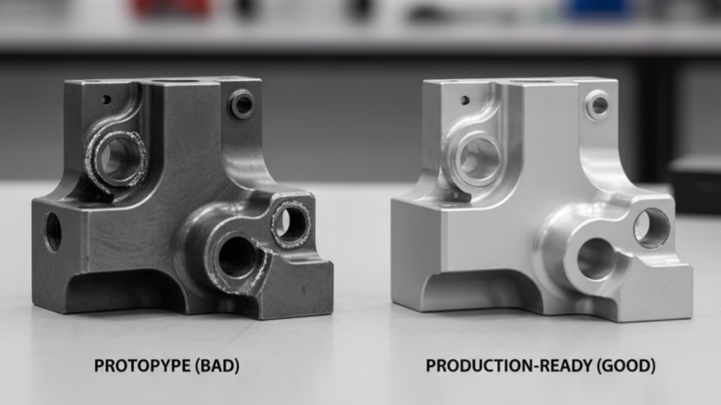
Ever wonder why your “perfect” CAD design gets quoted at a sky-high price or, worse, gets a “no-quote”? It’s likely due to a few common, yet costly, Design for Manufacturability (DfM) errors, such as those detailed in this guide to material selection.
This guide reveals the 5 biggest DfM mistakes common across all CNC machining and provides actionable steps to fix them. For advice tailored specifically to lathe work, see our DfM guide for CNC turned parts.
The most common and costly DfM mistakes in CNC machining include designing sharp internal corners that require special tooling, walls that are too thin to be rigid, deep pockets or holes with high aspect ratios, applying unnecessarily tight tolerances across the entire part, and specifying overly smooth surface finishes.
Now that you know what the main issues are, read on to see the specific data, expert advice, and a case study on how fixing these DfM mistakes saved one company over 70% on their part cost.
Quick Reference: Cost Impact of Common DfM Mistakes
Mistake 1: The Lure of Sharp Internal Corners
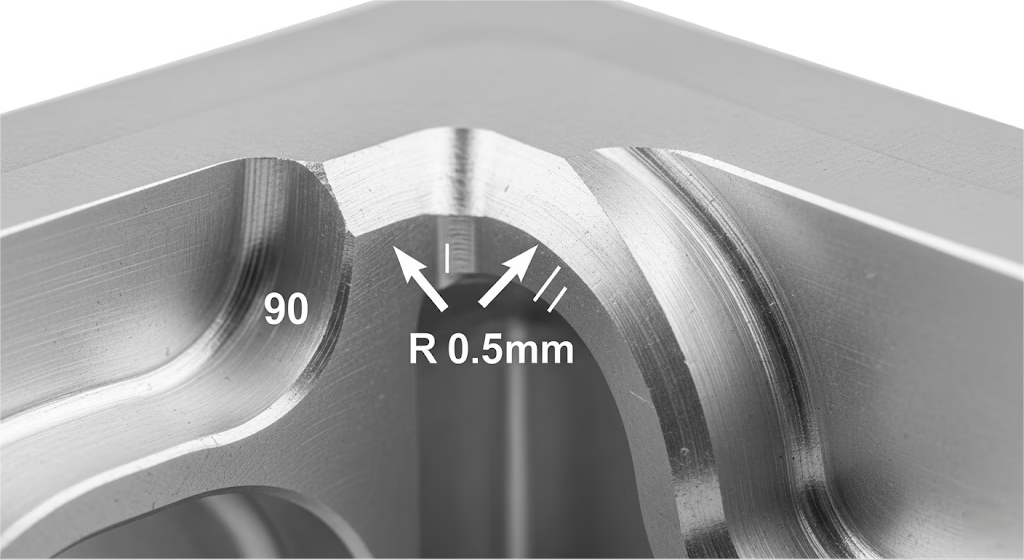
It’s a common sight in CAD models: a pocket or a slot with perfectly crisp, 90-degree internal corners.
Aesthetically, it looks clean and precise. But in the world of CNC machining, this feature is a significant cost driver, as we explore in our deep dive on internal sharp corners vs. radius.
Why? The reason is simple: CNC cutting tools are round. A round tool cannot create a perfectly square corner.
To achieve that sharp edge, your part has to be moved to a different, more expensive process like Electrical Discharge Machining (EDM).
A single corner processed with EDM can cost 3 to 5 times more than a corner machined with a standard end mill. This is a classic example of how a small design choice forces a major process change, a decision explored in our cost-benefit analysis for machining processes.
As Greg Paulsen, Director of Application Engineering at Xometry, often emphasizes, DfM is about achieving your design’s intent in the most efficient way. He notes, “Often, a very small, non-critical design tweak can be the difference between a $50 part and a $500 part.” That sharp internal corner is frequently one of those tweaks.
The Simple, Cost-Effective Solution
The fix is straightforward: design with a corner radius. By adding a radius, you allow a standard, round cutting tool to do the work efficiently. Here are two actionable rules:
- A Good Radius: Make the corner radius at least 1/3 of the cavity’s depth.
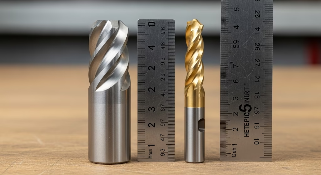
- A Better Radius: For maximum efficiency, design the radius to be slightly larger than the tool’s radius. For example, using a 12mm diameter tool (with a 6mm radius) to clear a pocket is far more efficient than using a tiny 3mm tool. The larger tool can remove material up to 8 to 16 times faster.
By simply adding a generous radius, you’re speaking the software’s language, leading to a faster, cheaper, and more accurate quote.
Mistake 2: Challenging Physics with Ultra-Thin Walls
In the quest for lightweight and compact designs, it’s tempting to push the boundaries of wall thickness. A design with sleek, slender walls can look great on screen, but it often creates significant problems on the machine shop floor, representing one of the most common CAD file errors that lead to rework.
your pursuit of quality, it’s easy to
To compensate, the machinist has no choice but to slow the machine down dramatically, taking very light, careful cuts. This isn’t a minor adjustment; for walls thinner than 0.5mm, this careful approach can increase machining time by 100% to 300%.
Furthermore, the risk of the part warping or breaking entirely increases substantially, which is why developing strategies for hard-to-machine superalloys is critical for high-stakes components.
For aluminum, walls thinner than 0.8mm are over 50% more likely to deform, and this challenge is even greater for difficult materials, as detailed in our guide to machining titanium. For plastics, that threshold is around 1.5mm.
How to Design for Stability and Strength
The solution is to respect the material’s limits—which vary significantly as shown in our plastic vs. metal DfM guide—and design with manufacturability in mind from the start.
- Follow the Guidelines: As a rule of thumb, stick to a minimum wall thickness of 0.8mm for metals and 1.5mm for plastics. If your design absolutely requires a thinner wall, be prepared for a significant increase in cost and lead time.
- Consider Ribs: If you need to add strength to a large, thin area, consider designing in support ribs rather than making the entire part thicker. This adds the necessary rigidity without a substantial increase in material or machine time.
Remember, a robust design isn’t just one that functions well in its final application; it’s one that can be manufactured reliably and cost-effectively.
Mistake 3: Ignoring the Tool in Deep and Narrow Features
Engineers love efficiency, so designing a part with a deep pocket or a long, narrow hole to consolidate features seems like a smart move. However, this often overlooks a fundamental manufacturing challenge: tool access and chip evacuation.
A “deep” feature is defined by its aspect ratio—the ratio of its depth to its diameter or width. Once this ratio becomes too high, standard tools are no longer effective.
Consider drilling a hole. A standard drill bit performs well up to an aspect ratio of about 4:1. This is your cost-effective sweet spot.
What happens when you go deeper?
- At a 6:1 ratio, the cost to machine that single hole can increase by 100% to 150%. The machine must switch to a “peck drilling” cycle—drilling a little, retracting to clear chips, and repeating—which significantly increases the time.
- Pushing to a 10:1 ratio? Now you’re in a different league. Costs can skyrocket by 300% to 800%. This requires specialized, expensive gun drills and extremely slow processes to manage heat and prevent tool breakage.
The same logic applies to deep pockets milled with an end mill. The longer and more slender the tool, the more it’s prone to deflection and vibration, forcing the machinist to reduce cutting speeds and feeds, which, you guessed it, drives up the time and cost.
The Smart Approach to Depth
Before specifying a deep feature, ask yourself if it’s truly necessary.
- Can you redesign the part? Is it possible to achieve the same function by machining from both sides, effectively halving the aspect ratio of any given feature?
- Is the hole essential? If it’s for weight reduction, could a wider, shallower pocket achieve a similar result more economically?
Thinking about how a tool will access and function within your part during the design phase is a critical step in creating a cost-effective and manufacturable product.
Mistake 4: The High Cost of Unnecessary Precision
In your pursuit of quality, a key step is understanding how to prevent common manufacturing defects, as it’s easy to fall into the trap of specifying tight tolerances across your entire part.
You might set a default tolerance of ±0.05mm in your drawing’s title block, thinking it ensures every feature is made perfectly.
In reality, you’ve just made your part dramatically more expensive without adding functional value, as tolerance is one of the main machining cost drivers.
Manufacturing a part to a tight tolerance isn’t just about the cutting process. It’s a commitment to a more complex and expensive workflow. Each tightly-toleranced dimension requires:
- Slower machining speeds to ensure accuracy.
- More frequent and more expensive tool changes.
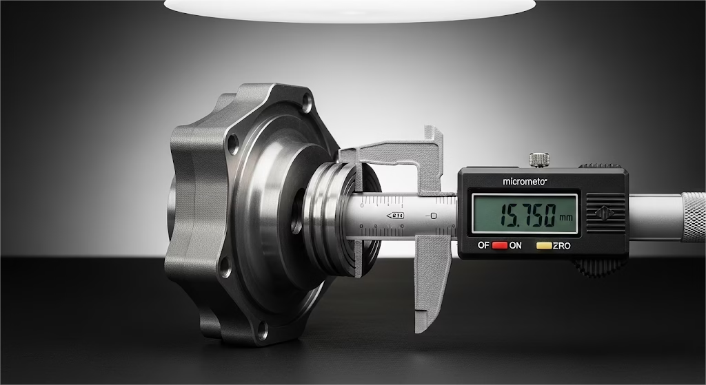
- Extensive inspection, often involving a Coordinate Measuring Machine (CMM), which can take more time than the machining itself.
The relationship between cost and tolerance isn’t linear; it’s exponential.
- Moving from a standard tolerance (e.g., ±0.1mm) to a precision one (±0.025mm) can increase the part’s cost by 50% to 200%.
- Demanding a high-precision tolerance (±0.005mm) can easily double or even quadruple the cost from there, as it often requires secondary grinding or lapping operations.
As Tony Holtz, an engineering manager at Protolabs, points out, “One of the most common cost drivers we see is unnecessarily tight tolerances. Engineers often apply a title block tolerance to the entire part when only one or two features are truly critical.”
A Real-World Example: The $300 Medical Housing
We recently worked with a medical startup whose aluminum housing design was quoted at $300 per unit. A primary reason was a global tolerance of ±0.05mm applied to the entire part.
We sat down with their designer and asked a simple question: “Which surfaces are absolutely critical for function?” It turned out only two surfaces needed that precision for assembly.
By relaxing the tolerance on all non-critical features to a standard ±0.2mm, we helped them reduce the final cost to just $85 per unit—a 70% reduction without sacrificing a single bit of functionality.
The Solution: Tolerance with Intent
Instead of a blanket tolerance, analyze your design feature by feature.
- Identify Critical-to-Function (CTF) features: These are mating surfaces, bearing bores, or press-fit locations. Apply your tight tolerances only here.
- Relax everything else: For non-critical features, a standard tolerance is more than sufficient and far more economical.
This intentional approach tells your manufacturing partner where to focus their efforts, ensuring you only pay for the precision you truly need.
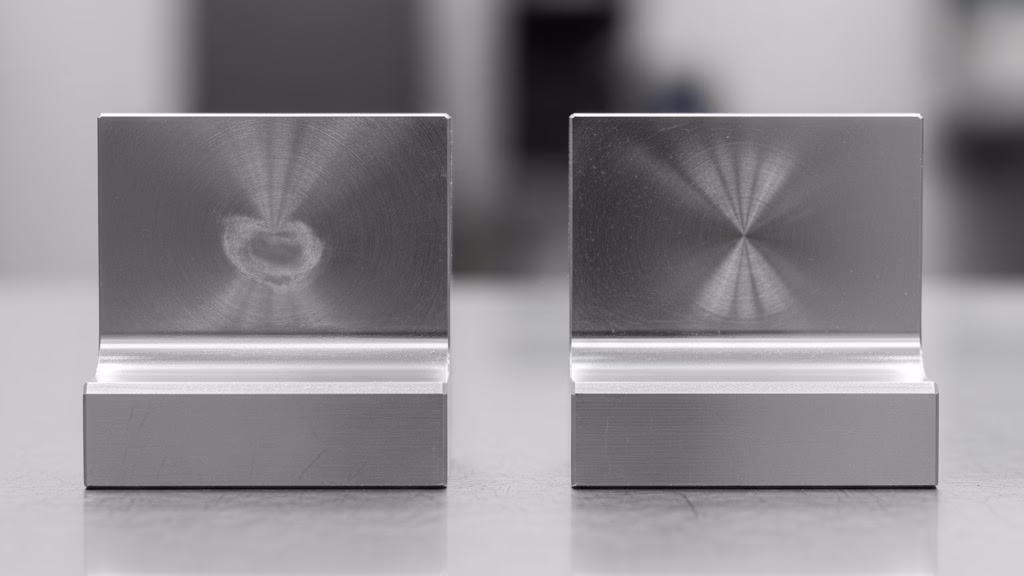
Mistake 5: Overlooking the Cost of Surface Finish
A beautiful, smooth surface finish or a sharply engraved logo can elevate a product’s perceived value. However, when performance is the goal, choosing the right functional coating is critical, as explained in this guide to Type II vs. Type III anodizing.
The surface finish from a standard CNC machining operation is typically around Ra 3.2 μm, which is perfectly functional for most applications.
Demanding a smoother finish requires extra steps, and each step adds cost.
- Improving the finish to Ra 1.6 μm might require an additional fine-finishing pass, increasing the cost by 10% to 25%.
- A very smooth Ra 0.8 μm finish often requires light polishing or grinding, adding 30% to 60% to the cost.
- Achieving a mirror-like finish of Ra 0.4 μm or better necessitates expensive and time-consuming secondary operations like lapping and polishing, which can easily double the part’s total cost.
Similarly, engraving text or complex logos directly with a CNC mill is a surprisingly slow process. The small tool must trace every single line, which can take longer than machining the rest of the part combined.
The Smart Way to Specify Finishes
Before defaulting to a very smooth finish, consider its purpose.
- Is it functional? A smoother finish is necessary for sealing surfaces or bearing journals, but for most external, non-contact surfaces, the standard finish is sufficient.
- Can you use a different process? For logos and text, consider laser engraving as a post-machining step. It’s significantly faster and cheaper than CNC engraving while producing a sharp, permanent mark.
By understanding these five common DfM mistakes in CNC machining, you can avoid costly pitfalls and create designs that are efficient to produce. This knowledge is especially critical when dealing with advanced materials, as illustrated in this guide to high-performance plastics, bridging the gap between your design intent and the realities of manufacturing.
Your Actionable DfM Checklist
Theory is one thing, but putting it into practice is what counts. To help you apply these lessons directly to your work, we’ve created a simple checklist.
Before you export that final STEP file, run through these questions. It’s a quick-and-easy way to catch costly DfM mistakes before they ever reach a quote.
The DfM Self-Checklist:
- [ ] Internal Corners: Is every internal corner radius at least 3mm or, ideally, larger than the radius of the intended cutting tool?
- [ ] Wall Thickness: Have I respected the material’s limits? (e.g., >0.8mm for aluminum, >1.5mm for plastics).
- [ ] Hole & Pocket Depth: Is the depth of any hole or pocket less than 4 times its diameter/width? If not, is it absolutely essential?
- [ ] Tolerances: Have I applied tight tolerances only to critical-to-function (CTF) features and left all other surfaces with a standard tolerance?
- [ ] Text & Logos: Have I planned for text and logos to be applied via a cost-effective secondary process like laser engraving instead of CNC milling?
Your Goal Is to Create Value
Ultimately, Design for Manufacturability isn’t about limiting your creativity. It’s about empowering it. By understanding and respecting the physical process of how your part will be made, you can design products that are not only brilliant in theory but also achievable in reality.
Mastering these DfM principles does more than just lower costs and shorten lead times. It builds trust with your manufacturing partners and establishes you as a highly competent engineer who understands the entire product lifecycle.
By avoiding these common DfM mistakes, you’ve taken the first step. The next is to master the underlying principles of CNC machining costs to ensure your great ideas always become great products, efficiently and economically.