Facing an “impossible” machining challenge with hardened steel or sharp internal corners? This definitive guide details exactly when you must use Wire Cutting (EDM). Learn our 3-step litmus test to make the right decision and avoid costly manufacturing failures.
Use Wire Cutting (EDM) on conductive materials when conventional machining fails due to three conditions: 1. The material is too hard for cutters (e.g., hardened tool steel >HRC 55). 2. The design requires sharp internal corners with a radius smaller than a physical tool can create (<R0.1mm).
Knowing when to use EDM is half the battle. Now, discover how to guarantee a perfect result. This guide reveals the process for achieving micron-level tolerances and provides a DFM checklist you can use today.
Where Conventional Machining Reaches Its Limits
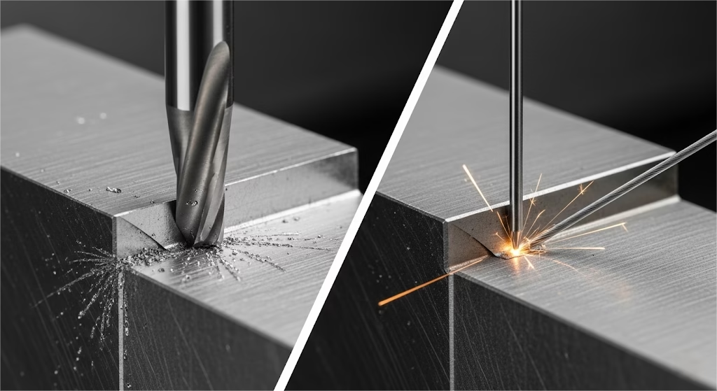
Before diving into the solution, it’s critical to understand why the conventional tools in your workshop—like CNC milling—fall short. The reasons aren’t about performance; they’re about the fundamental laws of physics which often require other advanced solutions like 5-Axis CNC Machining for different types of complex geometries.
First, there’s the hardness barrier. Traditional machining works because the cutting tool is significantly harder than the workpiece, but this becomes ineffective when working with materials where understanding the properties of hardened tool steels like D2 is critical.
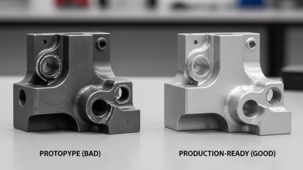
Next is the geometry barrier. A rotating milling cutter is round, and it will always leave a rounded internal corner equal to its radius. Even a tiny ø1mm endmill can only produce a corner with a R0.5mm radius at best. For designs that demand crisp, sharp internal corners, even advanced CNC milling services are geometrically incapable.
Finally, there’s the force barrier. Every milling cutter exerts mechanical force on a part, pushing and vibrating it. For components with ultra-thin walls (under 0.5mm) or delicate features, this stress can easily cause deformation, chatter marks, or outright breakage.
A 3-Step Litmus Test for Choosing Wire EDM
If your project hits any of the barriers above, it’s time to apply this simple litmus test. While this test confirms if you need EDM, our Wire EDM vs. Sinker EDM guide helps you decide which specific process to use.
If you answer “yes” to any of the following questions, Wire EDM is not just an option—it is the required solution.
The Material Hardness Test: Is Your Material Over HRC 55?
This is the most straightforward trigger. Understanding the core applications for wire EDM starts with hardness. Once a conductive material has been heat-treated, Wire EDM is the default process.
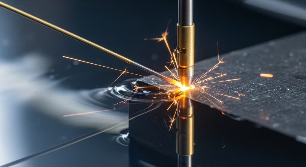
Because it operates based on the principles of this non-contact spark erosion process, it is completely indifferent to material hardness. This makes it the only reliable method for machining:
- Hardened Tool Steels (D2, A2, SKD11, etc.)
- Tungsten Carbide
- Titanium and Inconel Alloys
- Polycrystalline Diamond (PCD)
The Internal Geometry Test: Do You Need a Corner Radius Under 0.5mm?
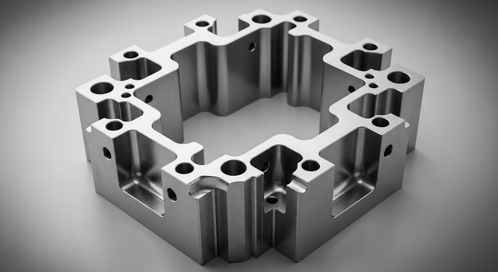
If your design requires a sharp internal corner for a perfect seal, a crisp product feature, or a precise fit, Wire EDM is the only answer.
By using an energized wire as thin as a human hair, the process can achieve geometric feats impossible for any rotating tool. Using a standard ø0.25mm wire, for example, we can consistently machine an internal corner with a radius of approximately R0.15mm.
The Part Delicacy Test: Can Your Part Withstand Mechanical Force?
If your component has ultra-thin walls or fine, delicate features, the physical force of a milling cutter introduces unacceptable risk.
The key benefit of Wire EDM here is stress-free machining. Since the electrode wire never physically touches the workpiece, no mechanical force is exerted. This completely eliminates the risk of deformation, vibration, and breakage, making it the ideal process for producing fragile parts like medical stents, thin mold inserts, and delicate electronics connectors, all while being completely burr-free.
From Decision to Success: A Guide to EDM Quality and Design
Knowing you need Wire EDM is the first step. Ensuring you get the perfect result requires understanding the process and preparing your design, which are key points in our checklist for choosing a high-precision manufacturing partner.
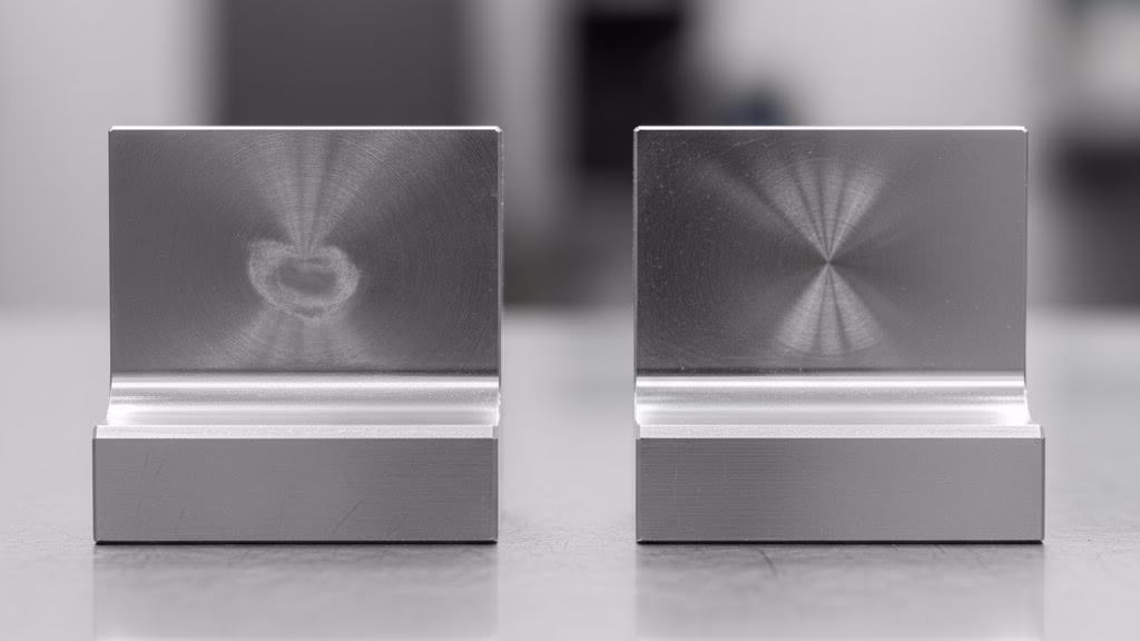
Specifying the Right Quality Grade
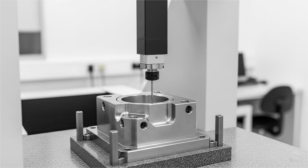
Not all Wire EDM finishes are the same. For high-precision work, subsequent “skim cuts” are performed with lower energy, and understanding the details of how EDM works to refine the surface is key.
As Brian Pfluger, an EDM expert at Makino, notes, modern machines are designed to “hold micron-level tolerances on fully hardened materials,” and this is how it’s done.
Understanding this allows you to specify exactly what you need.
| Machining Strategy | Achievable Tolerance | Typical Surface Finish (Ra) | Best For… |
| 1 Cut (Rough) | ±0.05mm | ~2.5μm | Prototyping, non-critical features |
| 2-3 Cuts (Fine) | ±0.01mm | ~0.8μm | Standard precision parts, mold inserts |
| 4-5 Cuts (Superfine) | ±0.003mm | <0.4μm | High-precision dies, optical molds |
DFM for Wire EDM: A Quick Checklist
To ensure a smooth process, consider these three points before sending your design for quoting:
- Provide a “Start Hole”: For any internal feature, the wire needs a place to start. Please design a small hole (ø0.5-1.0mm is typical) through which the wire can be threaded.
- Confirm Material Conductivity: The EDM process relies on electrical discharge. Your chosen material must be conductive.
- Consider Flushing Ports (Expert Tip): For deep, enclosed cavities, adding small, extra holes can dramatically improve how fluid flushes away eroded material. This can increase cutting speed and stability.
Conclusion: The Ultimate Solution for Manufacturing’s Toughest Challenges
When faced with materials too hard to cut, geometries too sharp to mill, and parts too delicate to handle, compromise is not an option. Wire Cutting (EDM) is more than just a process; it’s the definitive answer to a specific class of manufacturing’s most demanding problems.
The cost of Wire EDM should not be compared to other processes; it should be weighed against the immense cost of not being able to make your part at all.
If your project is facing one of these “impossible” challenges, don’t settle for a compromised design. Upload your CAD file today, and our Wire Cutting (EDM) specialists at Zenithin will provide a complimentary “Extreme Feature” manufacturability analysis report.