Stop gambling with 5-axis programming. This definitive guide moves beyond basic CAM functions and provides the strategic framework manufacturing engineers need to eliminate collisions, quote complex jobs confidently, and maximize machine ROI. We deliver the proven 5-axis toolpath strategies required for complex aerospace and medical components.
Effective 5-Axis Toolpath & Programming Strategies are a strategic framework balancing 3+2 machining (for setup reduction and ROI) against simultaneous 5-axis (for complex geometry). Success requires application-specific toolpaths, like Swarf Milling or Flowline, and a complete kinematic simulation (Digital Twin) to ensure collision-free operation.
Now that you understand the definition, it’s time to see the framework in action. Read on for the specific solution packages and expert insights—including the critical “singularity” trap—that CAM manuals won’t tell you.
Your First Decision (3+2 vs. Simultaneous 5-Axis)
As engineers, our first strategic decision when a complex part hits our desk is how to approach it. There’s a persistent myth that “real” 5-axis means simultaneous, continuous motion. This is wrong.
Let’s be clear: 3+2 positional machining is not the “low-cost version” of 5-axis; it is the most profitable version of 5-axis.
Industry experts have pointed out this reality for years. As Mike Titomi, former Director of Product at Mastercam, has often highlighted in technical talks, the vast majority of the immediate ROI for any shop moving to 5-axis comes directly from 3+2 programming.
Why? Because it attacks the single biggest source of waste in our process. Studies show that in a traditional 3-axis workflow, as much as 75% of total manufacturing time is spent on non-cutting activities. This is the time you burn on:
- Building multiple fixtures.
- Repeatedly setting up the part (Ops 10, 20, 30…).
- Re-indicating and finding your datums.
- Manually intervening between cycles.
The “Done-in-One” strategy enabled by 3+2 machining eliminates this waste. By accessing five sides of the part in a single clamping, you vaporize setup time and, just as critically, you eliminate the tolerance stack-up errors that creep in with every new setup.
When to Use Continuous 5-Axis Strategies
So, if 3+2 handles the bulk of the work, when do you deploy full simultaneous 5-axis toolpaths? You pull this trigger only when it solves a specific problem that 3+2 cannot. This decision is driven by three clear needs:
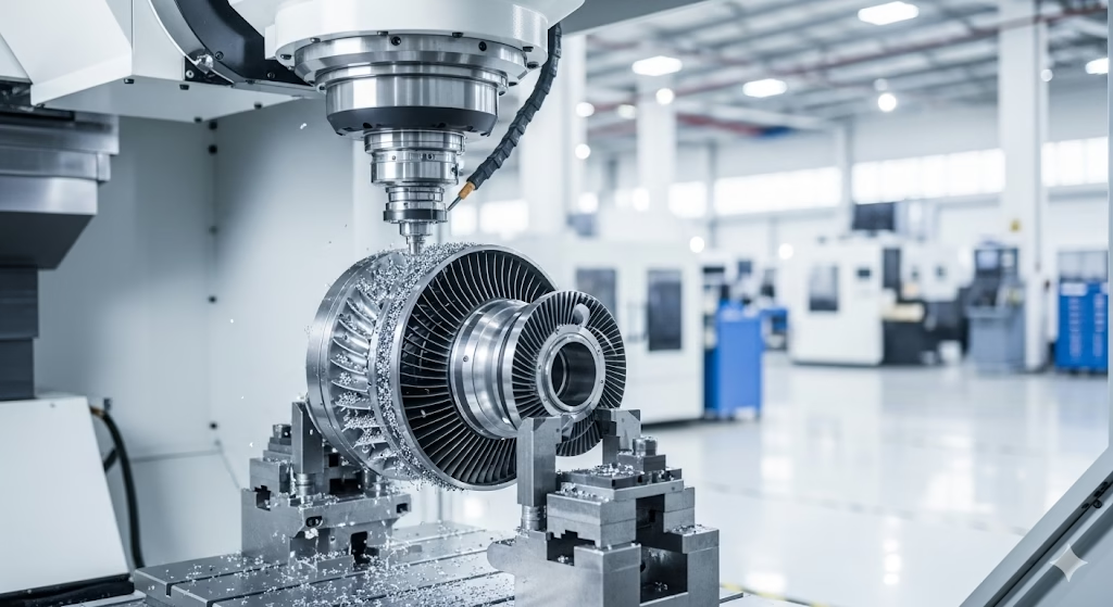
- Geometric Necessity: This is the obvious one. You simply cannot machine the part without simultaneous motion. This includes components like impellers, blisks, turbine blades, or engine ports where the tool must follow a complex curve while dynamically tilting to avoid the part itself.
- The Efficiency Mandate (Swarf): This is where you can make massive cycle time gains. Consider finishing a 5-degree tapered wall. A 3-axis ball-nose endmill must run hundreds of tiny step-overs to create a smooth surface, a process that could easily take 45 minutes. A 5-axis Swarf Milling strategy, which tilts the tool and uses the entire flank of the cutter, can machine that same surface in under 1 minute. That is a time saving of over 95%, achieved purely through better programming strategy.
- The Quality Mandate (Surface Finish): For complex surfaces like molds or medical implants, 5-axis finishing allows you to strategically tilt the tool. This creates a much larger “effective cutting radius” than the ball nose alone. This larger radius allows you to use a dramatically larger step-over while achieving the exact same (or better) cusp height (surface finish). You get a mirror finish in a fraction of the time.
The Engineer’s Decision Checklist
Use this simple checklist before starting any 5-axis job:
| Ask Yourself This: | If Yes… | If No… |
|---|---|---|
| Can I reach all machined features by indexing the part to a series of fixed angles? | Use 3+2 Strategy. | Move to the next question. |
| Does the part contain undercuts, helical channels, or surfaces (like an impeller blade) that physically require the tool to move and tilt at the same time? | Use Simultaneous Strategy (Necessity). | Move to the next question. |
| Can I replace a time-consuming 3-axis finishing path (using a ball nose) with a single 5-axis path using the tool flank (Swarf)? | Use Simultaneous Strategy (Efficiency). | Use 3+2 Strategy. |
Building Your Absolute Safety Framework
Let’s talk about that feeling in the pit of your stomach when you run a new 5-axis program—standing by the controller, hand hovering over the feed hold, even after watching a “perfect” simulation.
You feel that way because you intuitively know that the toolpath verification inside your CAM software (Strategy Layer 1) is only checking the cutter against the part. This is a necessary first step, but it is dangerously incomplete.
A collision that scraps a $20,000 part or damages a $500,000 machine rarely involves just the tool and the part. The real danger comes from the tool holder, the spindle head, the fixture bolts, or the machine table.
To prevent this, you must build a multi-layered safety firewall before you ever press cycle start.
Layer 1: The Digital Twin Machine Simulation
Your strategy must move beyond simple part verification and adopt a full Digital Twin. This isn’t just a visualization; it is a full kinematic simulation of your entire machining environment. Your simulation must include precise models of:
- The machine’s spindle head.
- The table, trunnion, or rotary axes.
- All fixtures, clamps, and vise jaws.
- The tool holder and full tool assembly (not just the cutter).
- The machine’s actual travel limits.
Only by running your toolpath within this complete virtual environment can you prove that the strategy is safe for the machine, not just the workpiece.
Layer 2: The Post-Processor Is Your Strategy
This brings us to the most critical and most overlooked layer of the safety system: your post-processor.
We are taught to see the post as a simple translator that converts our CAM toolpath into machine G-code. In 3-axis, this is mostly true. In 5-axis, this mindset is catastrophic.
In simultaneous 5-axis machining, your post-processor is an active decision-maker.
When your tool vector needs to tilt from one position to another, the post decides how to execute that move. It must solve complex kinematic problems in real-time. For example:
- Does the machine rotate the C-axis clockwise +350 degrees?
- Or does it unwind counter-clockwise -10 degrees to reach the same vector?
A generic or poorly configured “universal post” might choose the +350-degree path, forcing the machine to suddenly stop, rapidly unwind its rotary axes mid-cut, and plunge back into the material. This single bad decision destroys the surface finish, breaks the tool, and is completely invisible in your original CAM simulation.
Your 5-axis strategy must include using a proven, machine-specific post-processor built specifically for your machine’s unique kinematics.
Layer 3: The Final Firewall—G-Code Simulation
The risk introduced by the post-processor leads us to the final, mandatory layer of defense: G-Code Simulation.
You must stop trusting the CAM data and start verifying the final output code. G-code simulation software (like VERICUT or the advanced simulators within platforms like Siemens NX) does exactly this.
It runs the actual G-code text file—the same file you put on the USB drive—against your Digital Twin.
This is the only process that catches kinematic errors, post-processor blunders, rapid move collisions, and vector flips introduced after the CAM stage. This is your ultimate safety net. It ensures the process you designed is the process that will actually run.
Application Solutions for Critical Problems
A robust safety framework prevents collisions, but a smart toolpath strategy wins quotes and makes the job profitable. For world-class results, mastery in implementing 5-axis strategies is essential.
This applies not just to engineering parts, but also to high-end complex custom figurines where artistry and 3D translation are key. When a complex RFQ lands on your desk, your ability to quote it depends entirely on this arsenal.
Too often, we get trapped in the “Efficiency vs. Quality” loop: to get the required surface finish, we use tiny step-overs that send cycle times skyrocketing, destroying our profit margin.
These strategies break that cycle. They aren’t just CAM features; they are specific solution packages for the problems that stop shops from bidding on high-value aerospace, medical, and mold work.
Master True 5-Axis Machining
Your strategy is sound, but it requires world-class execution. Our true 5-axis machining services deliver the complex geometries and tight tolerances your aerospace, medical, and high-tech components demand. Let us turn your most complex strategies into reality.
Solution Package A: The Swarf Milling Strategy
- Target: Tapered walls, thin-wall structures, and drafted surfaces (common in mold cores and aerospace structural parts).
- The Problem: Finishing a 5-degree tapered wall with a 3-axis ball-nose endmill is painfully slow. You are cutting with the very tip of the tool, forcing hundreds of passes to achieve a smooth finish. This can easily take 45 minutes.
- The 5-Axis Solution: Swarf Milling is the strategy of tilting the tool so the entire flank (side) of the cutter machines the tapered wall in a single, continuous pass.
- The Result: That 45-minute cut is now finished in under 1 minute. This 95%+ time reduction isn’t just an optimization; it’s a fundamental change in capability. The strategic challenge here isn’t just using the path; it’s controlling the tool corners (how it rolls around edges) and ensuring the tool tilt doesn’t gouge the part floor.
Solution Package B: The Complex Surface Strategy
- Target: Complex, free-form surfaces (molds, medical implants, turbine blades).
- The Problem: The “Cusp Height” trap. To get a mirror finish (a low cusp height), the formula dictates a tiny step-over, leading to massive cycle times.
- The 5-Axis Solution: Use a Multi-Axis Flowline or Contour strategy. The key here is not just following the curve; it’s the tool tilt (known as lead and lag). By strategically tilting the tool (e.g., 15 degrees forward), you change the geometry of the cut. You are no longer cutting with just the 6mm radius of the ball-nose; you are cutting with a massive “effective radius” of that tilted tool.
- The Result: You can now use a step-over that is 3x or 4x larger while achieving the exact same low cusp height. You break the efficiency-quality trap: you get the mirror finish in a fraction of the time.
Solution Package C: The Automated Channel Strategy
- Target: Impellers, blisks, and engine ports (deep, curving, inaccessible channels).
- The Solution: Use a specialized, automated module like Impeller Machining or Port Machining. The strategy here is trusting automation. Instead of you trying to program thousands of individual tilt vectors, these paths only require key inputs (like the blade profile, the splitter, and the hub floor). The software then automatically calculates the optimal, collision-free tilt paths to machine the entire component.
Solution Package D: The Foundational Roughing Strategy
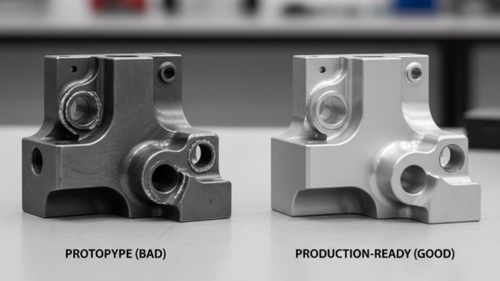
This final package is the most important one, and it brings us back to that scrapped $20,000 Inconel impeller.
That catastrophic failure on the final finishing pass had nothing to do with the finishing toolpath. The failure was locked in hours earlier by a flawed roughing strategy.
The original engineer used a standard 3-axis top-down roughing program. This common approach left large, uneven scallops of material deep in the channel corners and near the hub. To reach these areas (and avoid the remaining material), the engineer was forced to program the finishing pass with a long, thin tool held in a bulky, extended holder.
It was that bulky holder—required only because of the bad roughing pass—that collided with the adjacent blade.
The Correct 5-Axis Strategy: We fixed the process by completely changing the roughing. We switched to a 5-axis Dynamic Roughing strategy using a short, rigid, “stubby” cutter.
Instead of attacking from the top down, we used 5-axis motion to tilt that short, rigid tool deep into the channel. It peeled material away layer by layer, starting from the outside and working its way in. This 5-axis strategy cleared 100% of the bulk material safely and evenly.
Because the roughing pass was perfect, the finishing pass was easy. We could now use a short, rigid, standard holder, completely eliminating the collision risk.
The Lesson: 90% of your finishing failures are caused by a poor roughing strategy. Your primary goal must be to use 5-axis roughing to create a perfectly clean, safe, and consistent environment for your finishing tools.
Solving Fatal Problems Not in the CAM Manual
This next section is critical. It covers the problems that your CAM simulation will always pass, yet will cause a catastrophic failure on the machine floor. These are the issues that create a massive gap between the “perfect” digital program and the chaotic physical reality.
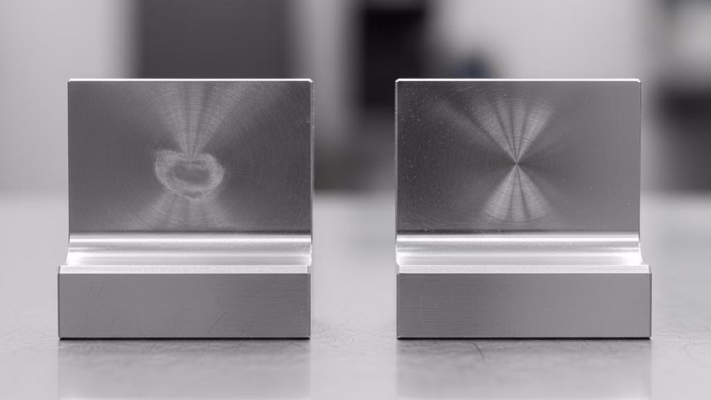
Gotcha #1: The Machine “Singularity” Trap
Let’s paint a picture. Your simulation is flawless. The tool moves smoothly over the part. You run the program, and halfway through, the machine violently jerks. The C-axis attempts to spin 180 degrees in a fraction of a second, the entire machine shakes, and you get a servo alarm.
This wasn’t a CAM bug. You just hit the machine’s singularity point.
This is a physical and mathematical trap baked into the design of most 5-axis trunnion (table-table) machines. When the tool vector is programmed to be perfectly vertical (A-axis = 0) and pass directly through the center of rotation, the machine controller panics. At that single point, there are infinite C-axis solutions to maintain the tool’s position, and the controller doesn’t know how to get from point A to point B without an instantaneous 180-degree flip.
Your Strategic Solution is NOT in the CAM Software.
Stop trying to program your way around this. Don’t spend hours trying to force the tool vector to “wobble” around the pole. The solution is 10 times simpler and happens at the setup stage.
The Strategy: Before you even set your G54, you need to load your entire fixture and workpiece onto the machine table, and a best practice is to do so at an intentional 15 or 20-degree angle.
This simple, physical setup change strategically shifts your entire machining envelope away from the machine’s built-in singularity pole.
With this one 10-minute setup decision, you have permanently eliminated a problem that could take 10 hours to (imperfectly) fix in programming.
Gotcha #2: Trusting the “Default” Tool Axis
Here’s the second common trap. Your toolpath machines the part successfully, but you watch the machine and it’s… erratic. The rotary axes are constantly making small, jerky, unnecessary adjustments instead of one fluid motion. This vibration translates directly to a poor surface finish and accelerates machine wear.
The cause? You left the “Tool Axis Control” on its default “automatic” setting.
When on auto, the CAM software is only calculating the minimum tilt required at every single point just to avoid a gouge. It is not calculating for the smoothest possible machine motion.
Your Strategic Solution: Take Manual Control of the Vector.
A world-class 5-axis program is often defined more by a smooth tool axis motion than a smooth toolpath. You must take manual control away from the software’s “automatic” guess. Instead of letting the tool vector flop around, define it yourself:
- Lock the tilt: For many surfaces, you can simply lock the tool at a fixed 15-degree lead angle.
- Drive from a curve: The best strategy is to create a separate, simplified “control curve” that is much smoother than the actual part surface. You then command the tool axis vector to follow that smooth curve, while the tool tip follows the complex cut path. This forces the machine’s rotary axes into a single, fluid, predictable motion, which is the true secret to achieving a mirror finish.

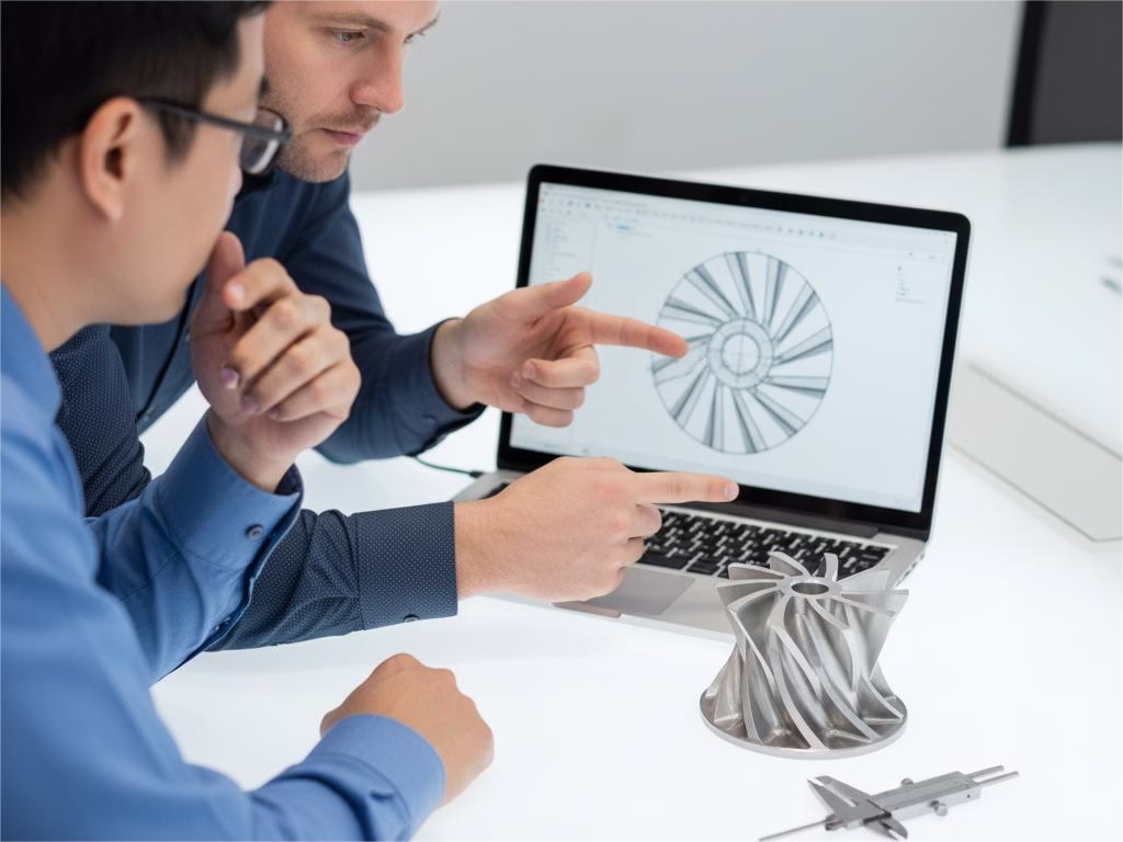
Conclusion: You Are Not a Programmer; You Are a “Manufacturing Strategist”
The path to 5-axis success is not paved with complex functions or the latest CAM software update. As we’ve seen—from the $20,000 impeller scrap to the singularity trap—success is built on a complete, closed-loop strategic framework.
It’s a framework that begins not in the CAM system, but at the machine setup, where a simple 15-degree part rotation can defeat a catastrophic singularity. It’s a process defined by a conscious strategic choice between 3+2 positioning (for profit) and simultaneous motion (for necessity).
It’s a workflow built on the hard-won knowledge that your post-processor is an active decision-maker, and that the only program you can trust is the final, verified G-code.
Your true role as an engineer is to stop being just a “CAM operator” focused on which button to click. Your value is in becoming the “manufacturing strategist” for your company—the one who defines the entire process, systematically mitigates every point of risk, and builds the reliable 5-Axis Toolpath & Programming Strategies that unlock new capabilities and create predictable profit. This guide is your first strategic playbook.
References & Notes
[1] Total Manufacturing Time Analysis: The “75% waste” statistic reflects widely cited lean manufacturing principles (like the Seven Wastes, or ‘Muda’) applied to traditional machining workflows. This time is consumed by non-value-added setup, transport, and waiting, all of which are drastically reduced by “Done-in-One” 5-axis strategies.
[2] Digital Twin & Simulation: A Digital Twin in this context refers to a complete, high-fidelity virtual model of the physical CNC machine, including its exact kinematics, controller logic, and all workholding components, as defined by industry leaders in manufacturing simulation.
[3] Kinematic Singularity: This is a fundamental concept in robotics and machine tool design. It is a point in the machine’s workspace where the controller loses the ability to determine a unique solution for the inverse kinematics, preventing stable movement in a specific direction. Our strategic avoidance (tilting the part setup) is the universally accepted best practice.